Electronic Financial Transaction Cards and Methods

a technology of electronic financial transaction and electronic cards, applied in the field of electronic security, can solve the problems of inability to communicate with secure processors, inability to fully adopt smart cards, and limited storage capacity of conventional transaction cards

Active Publication Date: 2012-08-16
DFS SERVICES
View PDF6 Cites 21 Cited by
  • Summary
  • Abstract
  • Description
  • Claims
  • Application Information

AI Technical Summary

Benefits of technology

[0015]A display can indicate which of multiple account selections has been made for a transaction. Buttons on the card can produce a chord, by activation of a combination of the buttons, and the chord can be used to alter functionality of the electronic card, such as instructing the card to enter a self-diagnostic mode.
[0016]A Smart Card reader device can be used to program and personalize the secure processor with an initialization data packet so that the secure processor can function in an operational mode which no longer requires use of the Smart Card reader device.

Problems solved by technology

There are many security problems with conventional transaction cards.
In addition to a lack of security, conventional transaction cards are also quite limited in storage capacity.
While broadly adopted abroad, Smart Cards have not been extensively adopted in the U.S. A major reason for this is the investment made by millions of merchants in legacy card readers, which cannot communicate with the secure processors of Smart Cards.
Also, Smart Cards conforming to the ISO 7816 standard suffer from their own limitations, including severely restricted I / O, an inability to provide “smart” transactions with legacy card readers, etc.
However, emulator cards, too, have their limitations.
Also, emulator cards do not address Smart Card protocols, as they are designed to work with legacy card readers.
Still further, the information that can be provided by the emulator card is limited to the amount of information that a conventional stripe can hold and that a legacy card reader can read.
These and other limitations of the prior art will become apparent to those of skill in the art upon a reading of the following descriptions and a study of the several figures of the drawing.

Method used


Image

  • Electronic Financial Transaction Cards and Methods
  • Electronic Financial Transaction Cards and Methods
  • Electronic Financial Transaction Cards and Methods

Examples


Embodiment Construction

[0061]Embodiments are disclosed which provide examples of enhanced electronic security. A number of non-limiting examples of transaction cards which address aforementioned problems and limitations of prior transaction cards are presented. As will be apparent to those skilled in the art, the methods and apparatus as disclosed herein are applicable to a wide variety of problems which require or could be improved with electronic security measures.

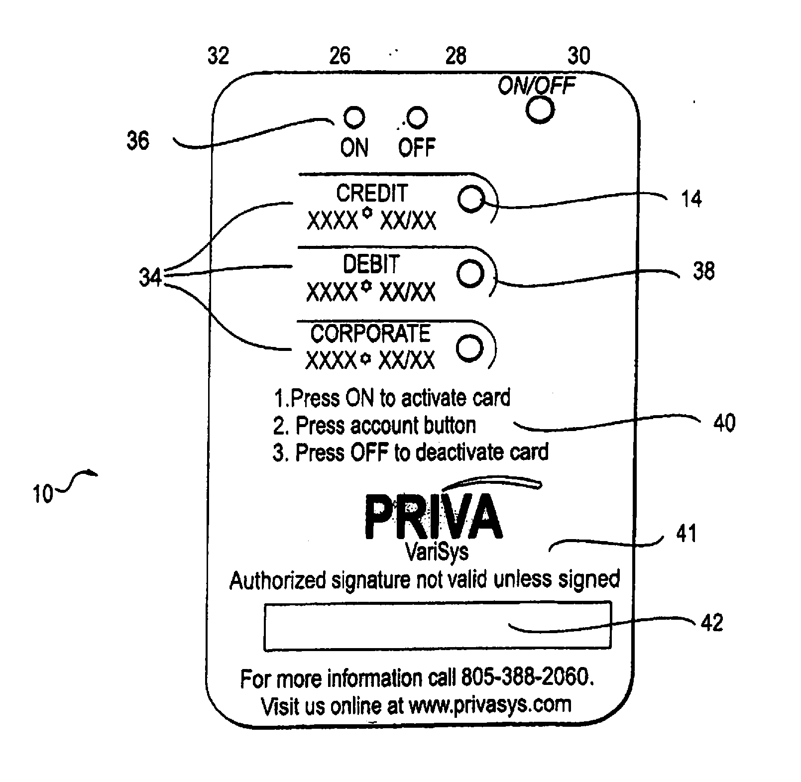
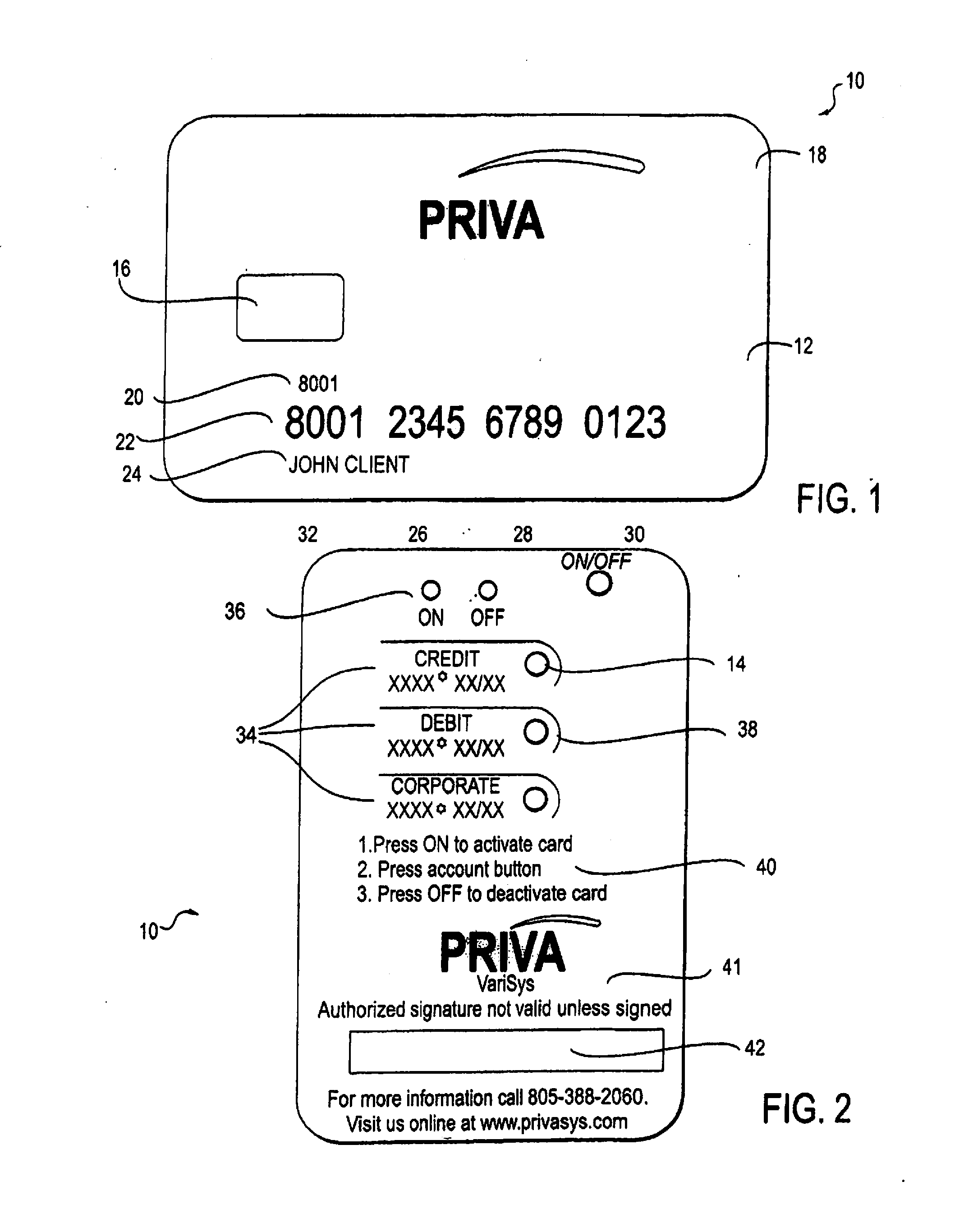
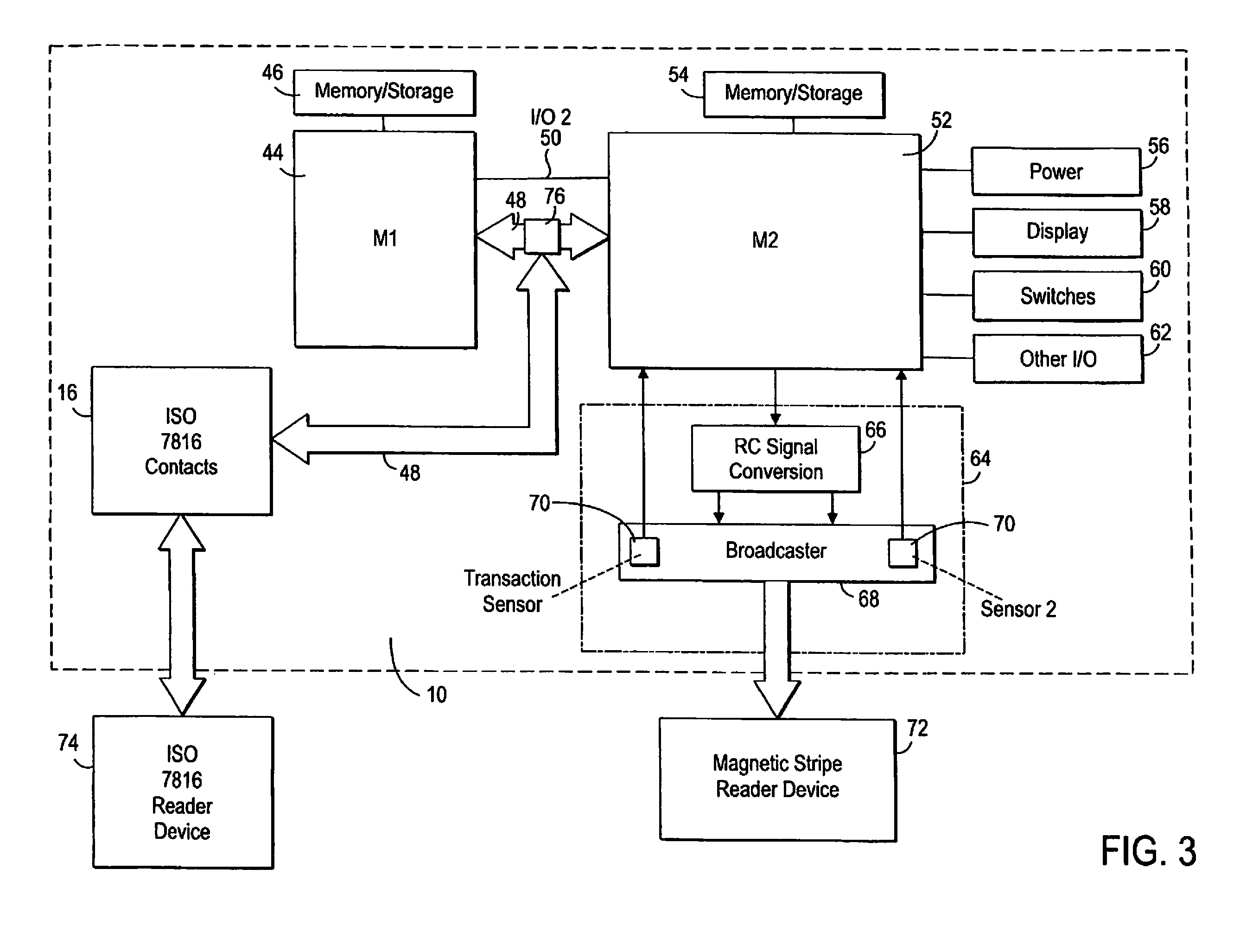
[0062]In one embodiment presented by way of example and not limitation, an enhanced Smart Card includes a card body, a secure processor and a general processor. The card body may be provided with an externally accessible card interface including a signal port, a power port, and a ground port. The secure processor is carried by the card body and is coupled to the signal port, the power port, and the ground port. The general processor is also carried by the card body, the general processor being coupled to a power source and being operative to p...


PUM


Abstract

An electronic card has a card body with a power source electrically coupled to a general processor which is electrically coupled to a secure processor and a broadcaster. At least one sensor sends a signal to the general broadcaster when a physical act of swiping the card body through a legacy magnetic stripe reader having a magnetic read head commences. The card is usable as a legacy mode Smart card, the broadcaster is operable to broadcast a transaction specific data packet so that it is read by the magnetic stripe reader, and the secure processor is an ISO 7816 compliant processor.

Description

CROSS REFERENCE TO RELATED APPLICATIONS[0001]The present application is a continuation application of U.S. patent application Ser. No. 13 / 102,991, filed May 6, 2011, which is a continuation of U.S. Ser. No. 12 / 726,868, now issued as U.S. Pat. No. 7,954,724, which was a continuation application of U.S. Ser. No. 11 / 413,595, filed Apr. 27, 2006, which claimed the priority benefit of U.S. Ser. No. 60 / 675,388, filed Apr. 27, 2005, all of which are specifically incorporated herein by reference. This application is also a continuation application of U.S. Ser. No. 11 / 391,719, filed Mar. 27, 2006, which claimed the priority benefit of U.S. Ser. No. 60 / 594,300 filed Mar. 26, 2005, both of which are specifically incorporated herein by reference. This application sets forth the disclosure of U.S. Ser. No. 11 / 391,719.BACKGROUND[0002]Exemplary embodiments disclosed herein pertain to electronic security. More particularly, exemplary embodiments disclosed herein pertain to electronic cards implemen...

Claims


Application Information

Patent Timeline
Patent Type & Authority Applications(United States)
IPC IPC(8): G06K19/073
CPCG06K19/0702G06K19/07722G06K19/077G06K19/06G06K19/07B42D25/21
Inventor POIDOMANI, MARKROUTHENSTEIN, LAWRENCEMCGUIRE, CHARLESALON, ZIV
Owner DFS SERVICES
Why Eureka
Try Eureka