
Light sensitivity calibration method and an imaging device

a light sensitivity and calibration method technology, applied in the field of imaging devices, can solve the problems of inability to acquire accurate results for conventional light sensitivity calibration, inability to maintain constant relationship between light sensitivity in preview mode and light sensitivity in capture mode, and inability to accurately achieve the calibration value of light sensitivity

Active Publication Date: 2012-08-16
ABILITY ENTERPRISE CO LTD
View PDF9 Cites 17 Cited by
  • Summary
  • Abstract
  • Description
  • Claims
  • Application Information

AI Technical Summary

Benefits of technology

[0008]In view of the foregoing, it is an object of the embodiment of the present invention to provide a light sensitivity calibration method and system that give considerations to both the light sensitivity calibration and the mechanical shutter calibration in order to arrive at an accurate calibration value of light sensitivity.

Problems solved by technology

However, due to characteristic differences among the image sensing elements, the relationship between the light sensitivity in a preview mode and the light sensitivity in a capture mode generally cannot be maintained constant.
As discussed above, the predetermined lag time is usually not consistent with a real mechanical shutter of the imaging device.
Accordingly, an accurate result for conventional light sensitivity calibration cannot normally be acquired.

Method used


Image

  • Light sensitivity calibration method and an imaging device
  • Light sensitivity calibration method and an imaging device
  • Light sensitivity calibration method and an imaging device

Examples


Embodiment Construction

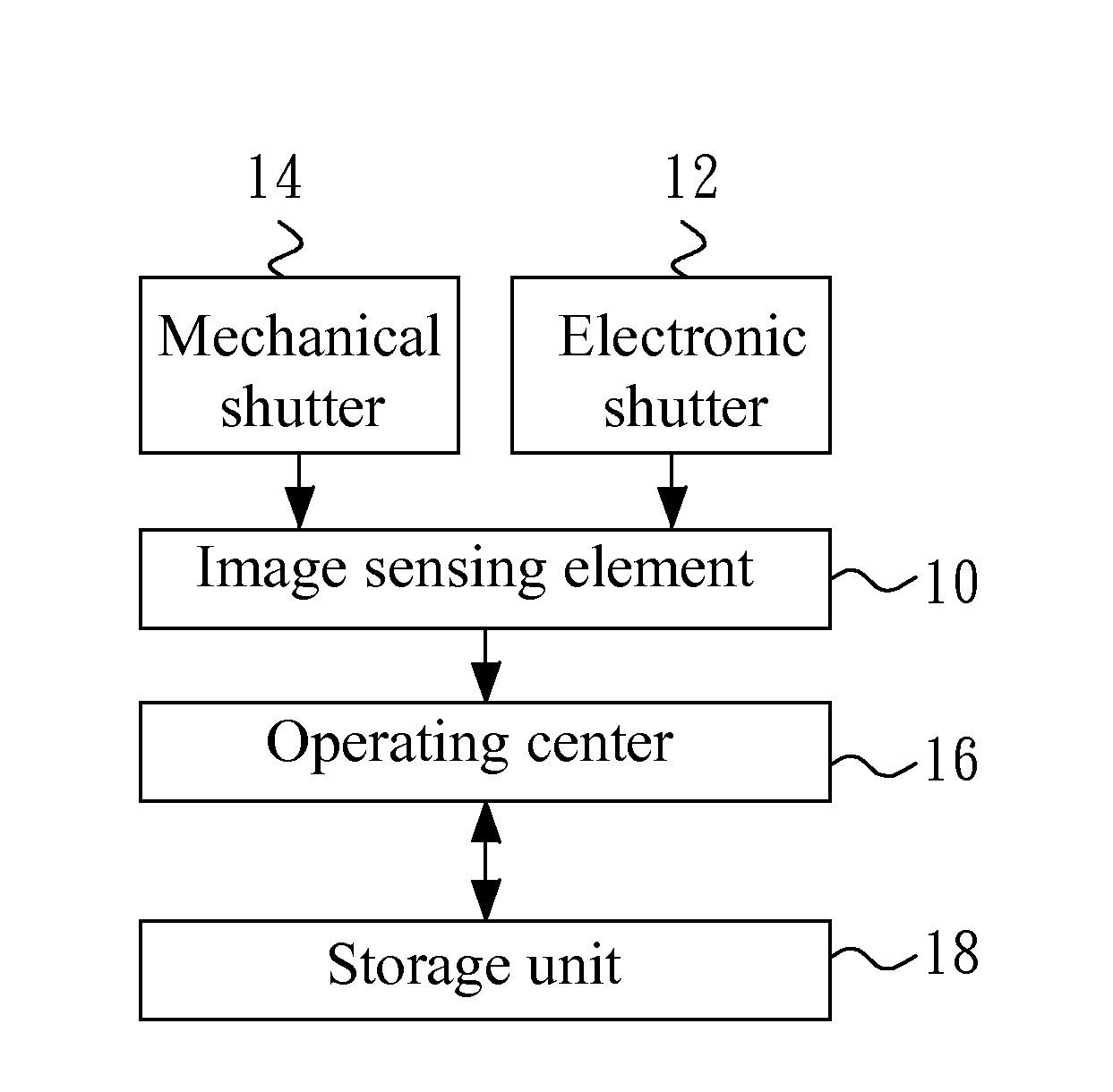
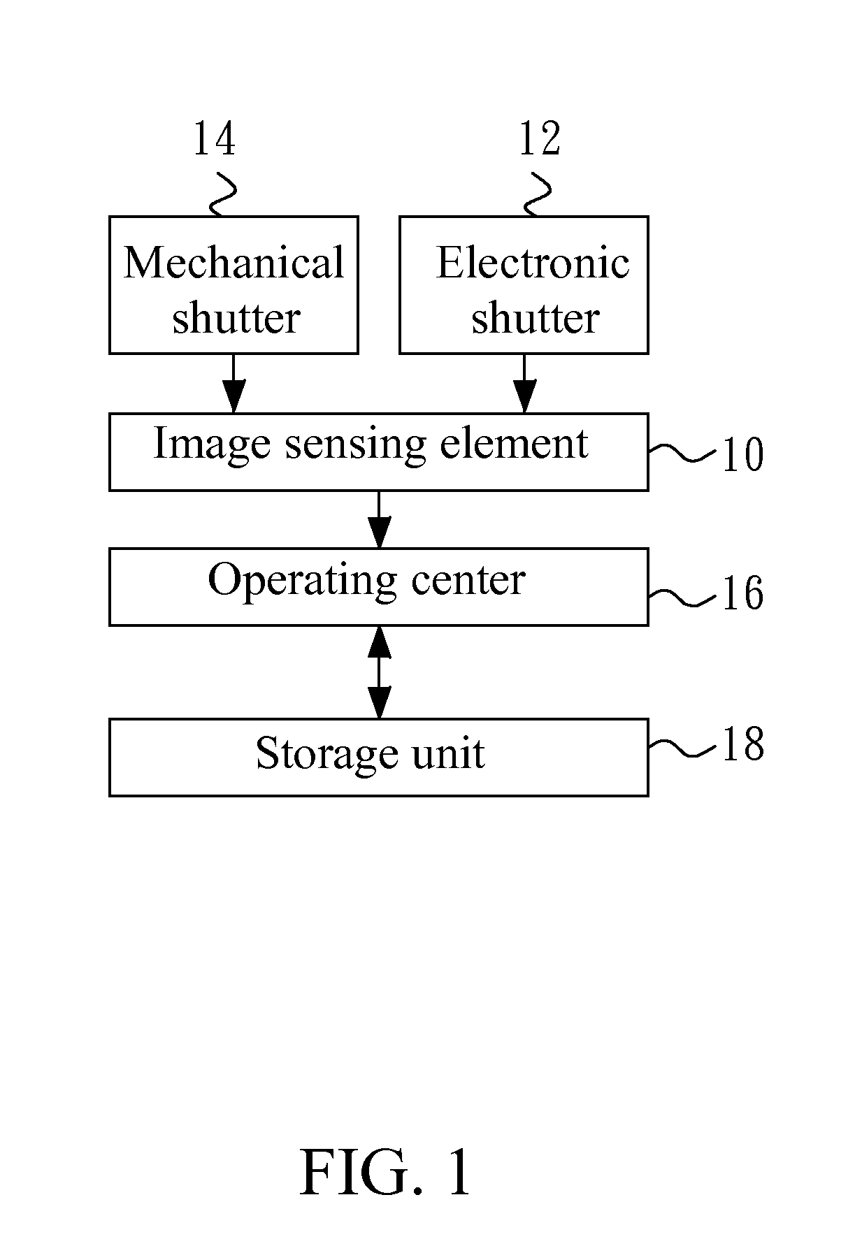
[0015]FIG. 1 shows a system block diagram of an imaging device according to one embodiment of the present invention. The imaging device may be, but is not limited to, a digital system with image capturing function, such as a digital video camera, a mobile phone, a personal digital assistant, a digital music player, a web camera or an image capturing and testing device.

[0016]Referring to FIG. 1, in the embodiment, the imaging device includes an image sensing element 10, an electronic shutter 12, a mechanical shutter 14, an operating center 16, and a storage unit 18. The image sensing element 10 is used to convert a light signal to an electric signal, and may be, but is not limited to, a charge coupled device or a complementary metal oxide semiconductor image sensor. Moreover, the electronic shutter 12 and the mechanical shutter 14 are used to control exposure time of the image sensing element 10. In a practical manner, the electronic shutter 12 is ordinarily used in the preview mode,...


PUM


Abstract

The present invention is directed to a light sensitivity calibration method and an imaging device. An exposure step is performed to obtain a light sensitivity according to a predetermined time. A time adjustment step is performed to adjust the predetermined time according to the light sensitivity, thereby obtaining an adjusted time. The predetermined time is replaced with the adjusted time and the exposure and time adjustment steps are repeatedly performed, until the adjusted time converges within a predetermined range.

Description

BACKGROUND OF THE INVENTION[0001]1. Field of the Invention[0002]The present invention generally relates to an imaging device, and more particularly to a light sensitivity calibration method and system.[0003]2. Description of Related Art[0004]An image sensing element is one of important components of an imaging device, and is used to convert a light signal to an electric signal suitable to be post-processed by a processing unit. However, due to characteristic differences among the image sensing elements, the relationship between the light sensitivity in a preview mode and the light sensitivity in a capture mode generally cannot be maintained constant. Therefore, a need has arisen to calibrate the light sensitivity of preview mode and the light sensitivity of capture mode respectively.[0005]An electronic shutter is ordinarily used to control exposure in the preview mode, and a mechanical shutter is ordinarily used to control exposure in the capture mode. The mechanical shutter has low...

Claims


Application Information

Patent Timeline
Patent Type & Authority Applications(United States)
IPC IPC(8): H04N5/235H04N23/75
CPCH04N5/23245H04N5/238H04N5/2352H04N23/667H04N23/72H04N23/75
Inventor CHEN, TAI-HUNGTSAI, YI-WENLEE, YIJIAN
Owner ABILITY ENTERPRISE CO LTD
Learn More