Thermoelectric-enhanced, vapor-compression refrigeration method facilitating cooling of an electronic component

a technology of electronic components and refrigeration methods, applied in the field of heat transfer mechanisms, can solve problems such as problems such as the difficulty of cooling at both the module and system level, and the approach becoming problemati

Inactive Publication Date: 2012-08-23
IBM CORP
View PDF2 Cites 15 Cited by
  • Summary
  • Abstract
  • Description
  • Claims
  • Application Information

AI Technical Summary

Problems solved by technology

This trend poses a cooling challenge at both the module and system levels.
However, this approach is becoming problematic at the rack level in the context of a data center.

Method used


Image

  • Thermoelectric-enhanced, vapor-compression refrigeration method facilitating cooling of an electronic component
  • Thermoelectric-enhanced, vapor-compression refrigeration method facilitating cooling of an electronic component
  • Thermoelectric-enhanced, vapor-compression refrigeration method facilitating cooling of an electronic component

Examples


Embodiment Construction

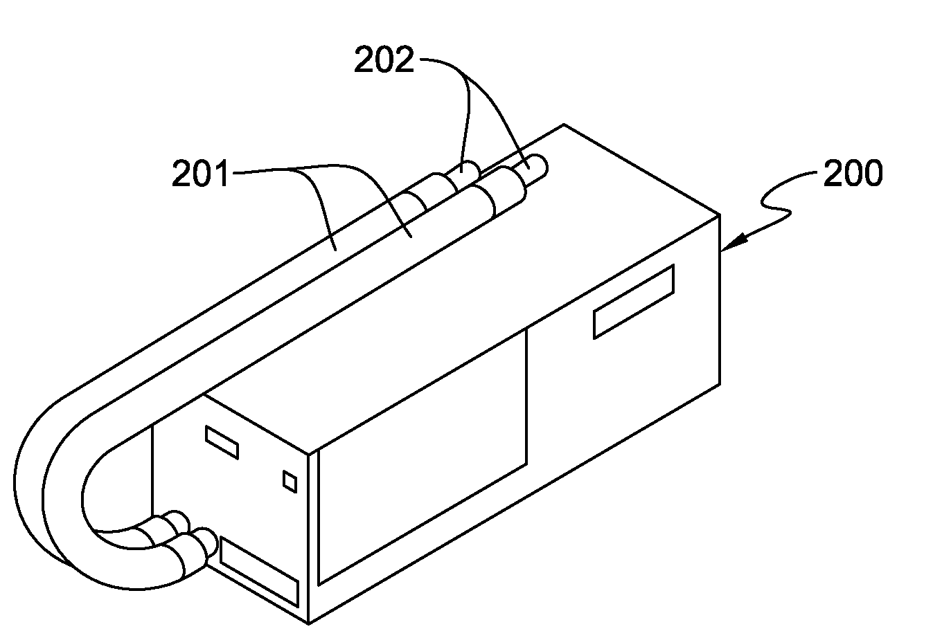
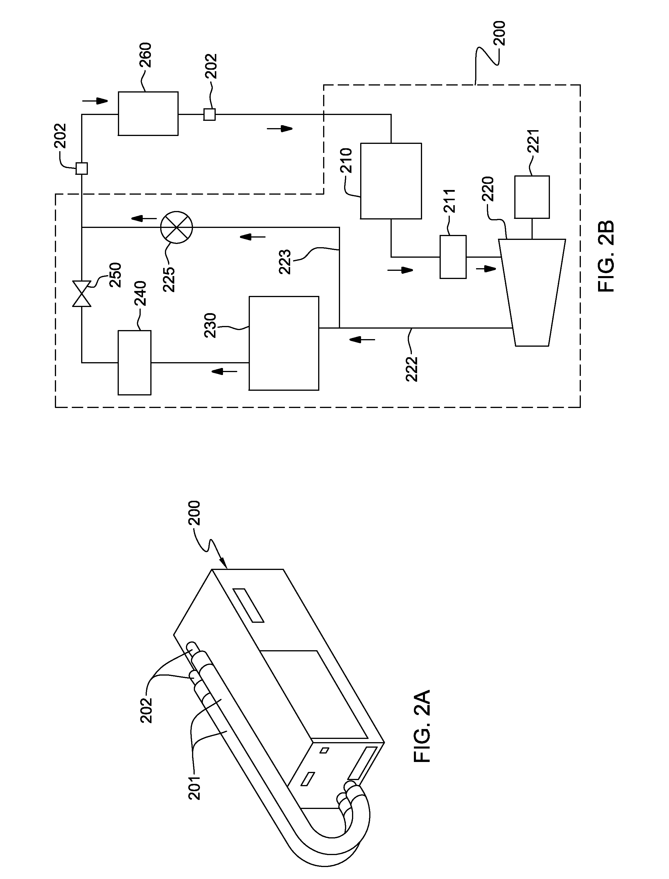
[0017]As used herein, the terms “electronics rack”, “rack-mounted electronic equipment”, and “rack unit” are used interchangeably, and unless otherwise specified include any housing, frame, rack, compartment, blade server system, etc., having one or more heat generating components of a computer system or electronics system, and may be, for example, a stand alone computer processor having high, mid or low end processing capability. In one embodiment, an electronics rack may comprise multiple electronic subsystems, each having one or more heat generating components disposed therein requiring cooling. “Electronic subsystem” refers to any sub-housing, blade, book, drawer, node, compartment, etc., having one or more heat generating electronic components disposed therein. Each electronic subsystem of an electronics rack may be movable or fixed relative to the electronics rack, with rack-mounted electronics drawers of a multi-drawer rack unit and blades of a blade center system being two e...


PUM


Abstract

A method is provided for facilitating cooling of an electronic component. The method includes: providing a refrigerant loop configured for refrigerant to flow through the loop; coupling a compressor in fluid communication with the loop, wherein a first portion of the loop resides upstream of a refrigerant inlet of the compressor, and a second portion resides downstream; and disposing a controllable thermoelectric array in thermal communication with the refrigerant loop. The thermoelectric array is disposed with the first portion of the refrigerant loop at least partially in thermal contact with the first side of the array, and the second portion of the loop at least partially in thermal contact with a second side of the array. The array is controlled to ensure that refrigerant in the refrigerant loop entering the compressor is in a superheated thermodynamic state.

Description

CROSS-REFERENCE TO RELATED APPLICATION[0001]This application is a continuation of U.S. Ser. No. 12 / 939,574, entitled “THERMOELECTRIC-ENHANCED, VAPOR-COMPRESSION REFRIGERATION APPARATUS FACILITATING COOLING OF AN ELECTRONIC COMPONENT,” filed Nov. 4, 2010, and which is hereby incorporated herein by reference in its entirety.BACKGROUND[0002]The present invention relates to heat transfer mechanisms, and more particularly, to cooling apparatuses, liquid-cooled electronics racks and methods of fabrication thereof for removing heat generated by one or more electronic components of the electronics rack.[0003]The power dissipation of integrated circuit chips, and the modules containing the chips, continues to increase in order to achieve increases in processor performance. This trend poses a cooling challenge at both the module and system levels. Increased airflow rates are needed to effectively cool higher power modules and to limit the temperature of the air that is exhausted into the comp...

Claims


Application Information

Patent Timeline
Patent Type & Authority Applications(United States)
IPC IPC(8): F25B21/02
CPCF25B21/02H05K7/20836F25B40/00
Inventor CAMPBELL, LEVI A.CHU, RICHARD C.ELLSWORTH, JR., MICHAEL J.IYENGAR, MADHUSUDAN K.SIMONS, ROBERT E.
Owner IBM CORP
Why Eureka
Try Eureka