Lane Departure Warning Apparatus and Lane Departure Warning System

Inactive Publication Date: 2012-08-23
CLARION CO LTD
View PDF9 Cites 55 Cited by
  • Summary
  • Abstract
  • Description
  • Claims
  • Application Information

AI Technical Summary

Benefits of technology

[0010]According to the present invention, it becomes possible to prevent false warnings and absence

Problems solved by technology

However, in JP Patent Publication (Kokai) No. 2009-298362 A, misrecognition of the one-side dividing line causes error in estimation of

Method used


Image

  • Lane Departure Warning Apparatus and Lane Departure Warning System
  • Lane Departure Warning Apparatus and Lane Departure Warning System
  • Lane Departure Warning Apparatus and Lane Departure Warning System

Examples


first embodiment

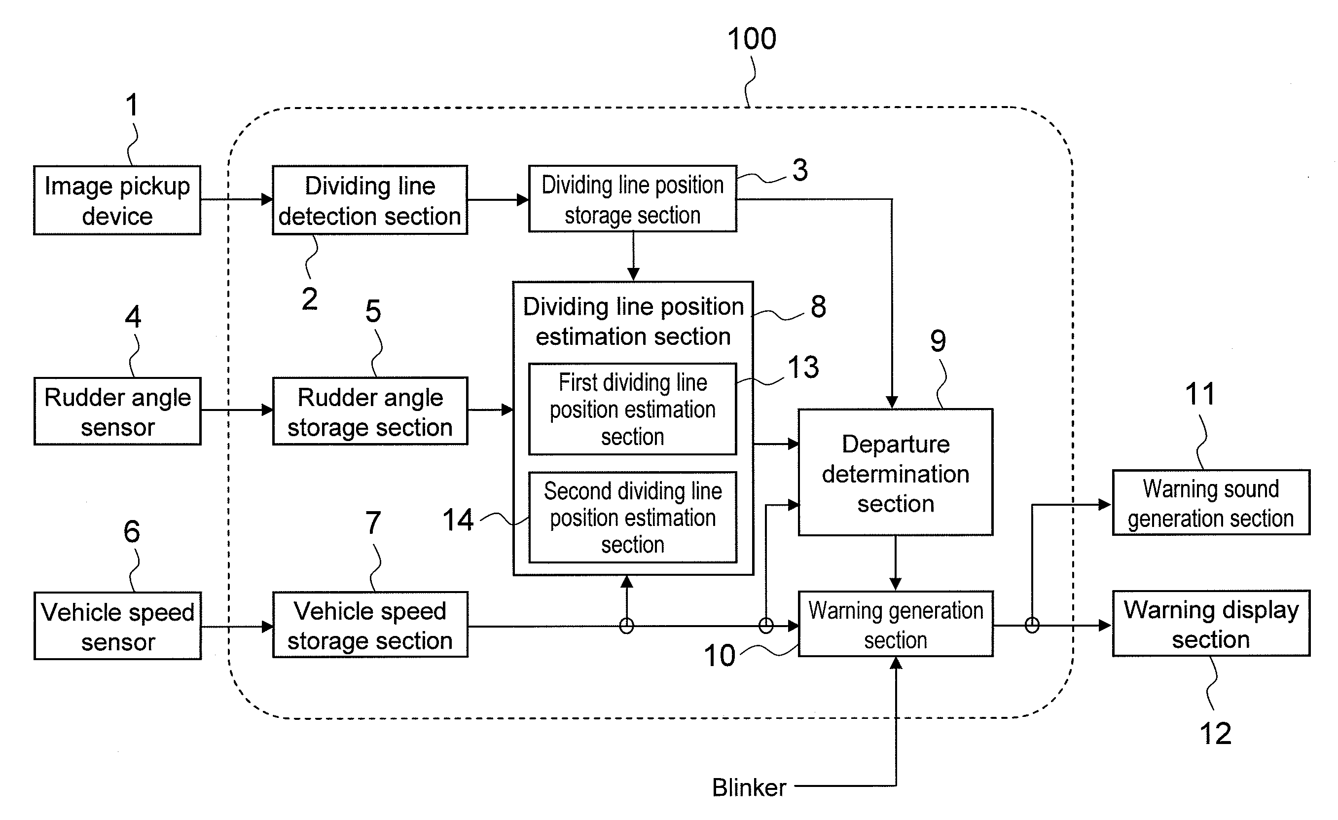
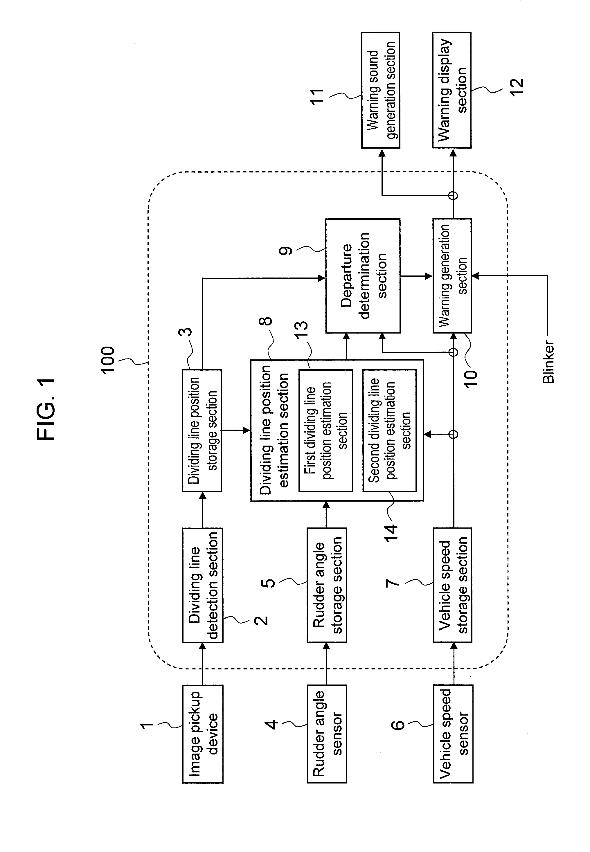
[0031]FIG. 1 is a schematic view of a lane departure warning system in a first embodiment.

[0032]The lane departure warning system comprises a lane departure warning apparatus 100, an image pickup device 1, a rudder sensor 4, a vehicle speed sensor 6, a warning sound generation section 11, and a warning display section 12.

[0033]First, a description will be given of structure and processing details of the lane departure warning apparatus 100.

[0034]The lane departure warning apparatus 100 comprises a dividing line detection section 2, a dividing line position storage section 3, a rudder angle storage section 5, a vehicle speed storage section 7, a dividing line position estimation section 8, a first dividing line position estimation section 13, a second dividing line position estimation section 14, a departure determination section 9, and a warning generation section 10 and is structured to have a program installed in an unshown computer of the lane departure warning apparatus 100 so a...

second embodiment

[0095]FIG. 9 is a schematic view of a lane departure warning apparatus 100 according to a second embodiment.

[0096]The lane departure warning apparatus 100 in FIG. 9 has a structure similar to the structure of the first embodiment (FIG. 1) except for the first dividing line position estimation section 13 and the second dividing line position estimation section 14 being removed.

[0097]A description will now be given of the processing details of the lane departure warning apparatus as a whole in the second embodiment.

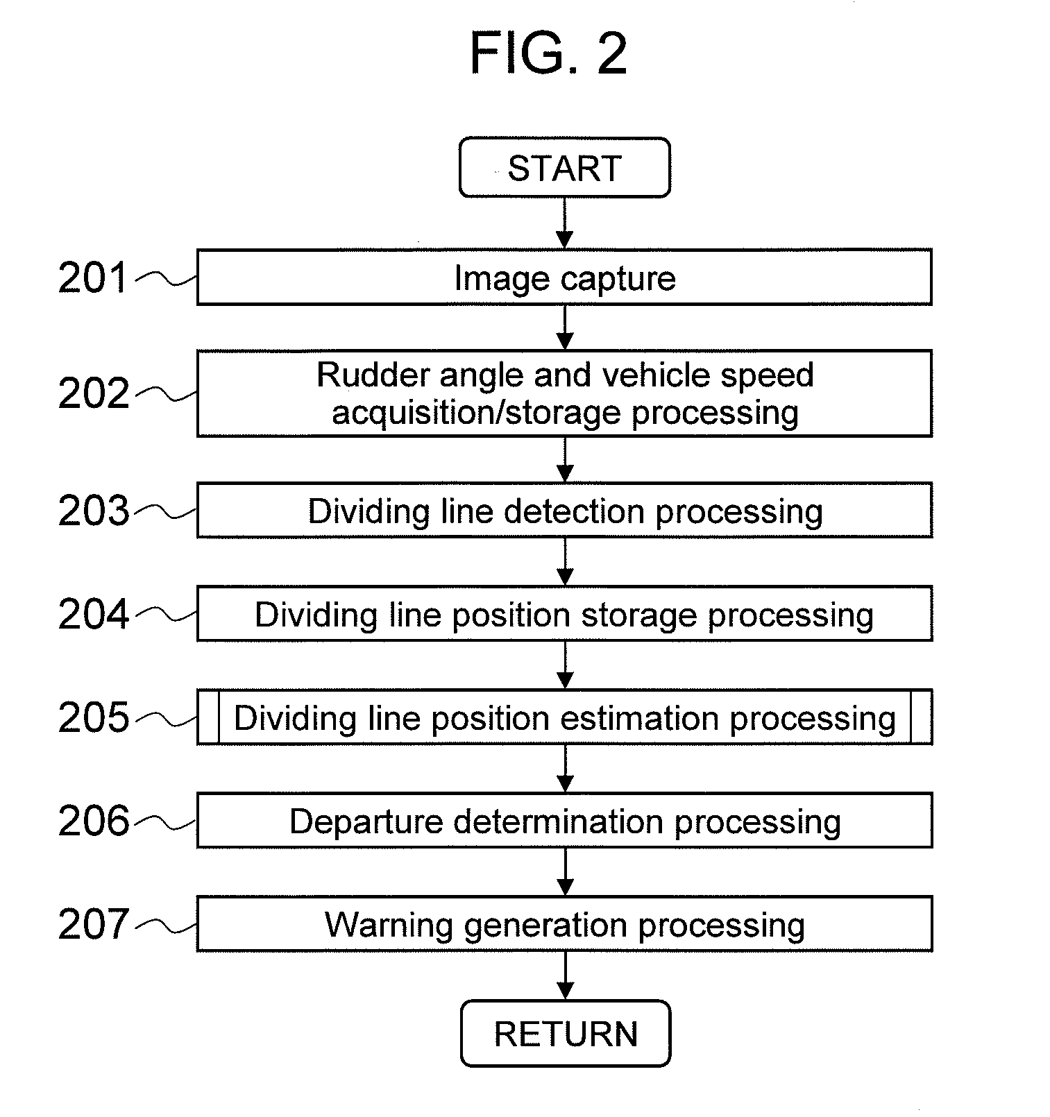
[0098]Although the flow chart indicating the processing details of the lane departure warning apparatus 100 is similar to the flow chart shown in FIG. 2, the processing step 205 for dividing line position estimation processing is different and so the processing will be described with reference to a flow chart of FIG. 10.

[0099]First, in a processing step 1001, it is determined whether or not a dividing line is now under estimation from the state of a dividing line estimating...

third embodiment

[0136]FIG. 16 is a schematic view of a lane departure warning apparatus 100 according to a third embodiment.

[0137]The lane departure warning apparatus 100 in FIG. 16 has a structure based on the structure in the second embodiment (FIG. 9) with a navigation 20 and a traffic information acquisition section 21 added thereto.

[0138]The navigation 20 is a device typified by car-navigation systems for calculating a vehicle position on a map, and since a method for calculating the vehicle position is publicly known, explanation thereof will be omitted. When special road geometries (branch roads, merging roads, tollgates, etc.) are present in a scheduled travel route near the vehicle, the navigation 20 outputs information including types of roads to the lane departure warning apparatus 100 with use of such communication means as an in-vehicle LAN.

[0139]The traffic information acquisition section 21 acquires the information inputted with such communication means as an in-vehicle LAN from the ...


PUM


Abstract

There is provided a lane departure warning apparatus capable of preventing false warnings and absence of a warning regarding lane departure which is attributed to special road geometries such as junctions and tollgates. The lane departure warning apparatus for outputting a warning signal upon determining departure of a vehicle from a lane, performing the steps of: when one dividing line in a vehicle width direction of the vehicle is non-detected, estimating a position of the one dividing line based on a position of the other dividing line as a first estimation dividing line; estimating a position of the non-detected one dividing line based on a position of the one dividing line prior to non-detection as a second estimation dividing line; and comparing the first estimation dividing line with the second estimation dividing line to determine lane departure.

Description

BACKGROUND OF THE INVENTION[0001]1. Field of the Invention[0002]The present invention relates to a lane departure warning apparatus for determining lane departure of a vehicle.[0003]2. Background Art[0004]Various technologies have been proposed for picking up images of the periphery of a vehicle by an in-vehicle camera and recognizing objects (e.g., vehicles and pedestrians), road markings and signs (e.g., traffic markings painted on the road such as dividing lines and “STOP” signs) in the picked-up images. For example, if it is possible to recognize dividing lines painted on the road on which a vehicle is travelling with an in-vehicle camera and to obtain the position of the vehicle in a lane, it becomes possible to issue a warning to a driver upon departure of the vehicle from the dividing lines or to control steering and braking of the vehicle so that the departure can be suppressed.[0005]As such systems for issuing a warning upon departure of a vehicle from a lane, there are Lan...

Claims


Application Information

Patent Timeline
IPC IPC(8): H04N7/18B60Q1/00
CPCG06K9/00798B60Q9/008B60W30/12B60W2420/42G08G1/167G06V20/588
Inventor IMAI, MASATOOKADA, TAKASHISAKATA, MASAO
Owner CLARION CO LTD
Why Eureka
Try Eureka