Lane departure warning system

a technology warning system, which is applied in the field of lane departure warning system, can solve the problems of changing the equipment or interior design of the vehicle, the installation of ldws is more troublesome and difficult, and the space inside the vehicle is limited, so as to achieve the effect of convenient and convenien

Active Publication Date: 2010-10-21
CREATE ELECTRONICS OPTICAL
View PDF11 Cites 19 Cited by
  • Summary
  • Abstract
  • Description
  • Claims
  • Application Information

AI Technical Summary

Benefits of technology

[0008]It is a further object of the present invention to provide a lane departure warning system(LDWS) that is disposed with a display such as liquid crystal display panel (LCD panel) for showing road images such as lane images captured by the camera. While being installed, the shot-direction of the camera can be adjusted to optimal position by the display so as to get best view of the road images. Moreover, the installation of the LDWS is more convenient and easier.

Problems solved by technology

However, the installation of LDWS affects circuits and equipments in vehicles and causes changes of the equipments or interior design of vehicles.
Thus the installation of LDWS is more troublesome and difficult.
Furthermore, the space inside the vehicle is limited.
The GPS and the LDWS need to be installed respectively and this is inconvenient for users.
Moreover, the GPS and the LDWS are independent from each other and unable to be integrated so that the cost of equipments and installation is increased.

Method used


Image

  • Lane departure warning system
  • Lane departure warning system
  • Lane departure warning system

Examples


Embodiment Construction

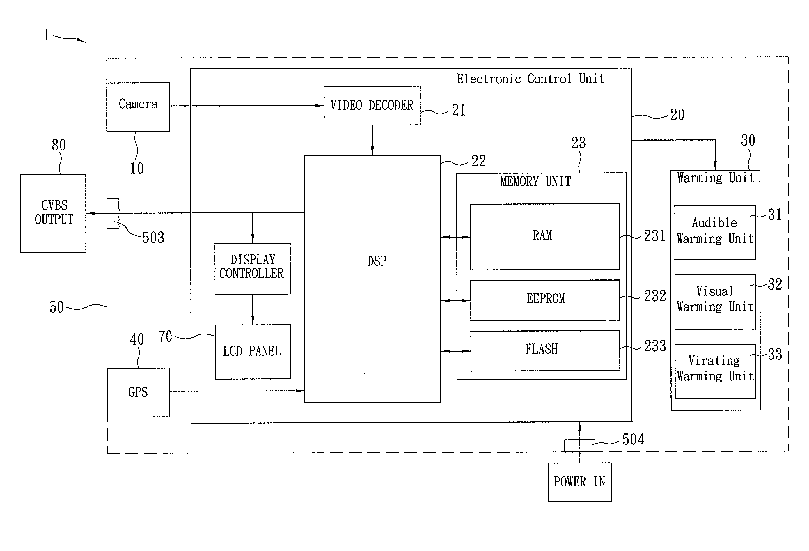
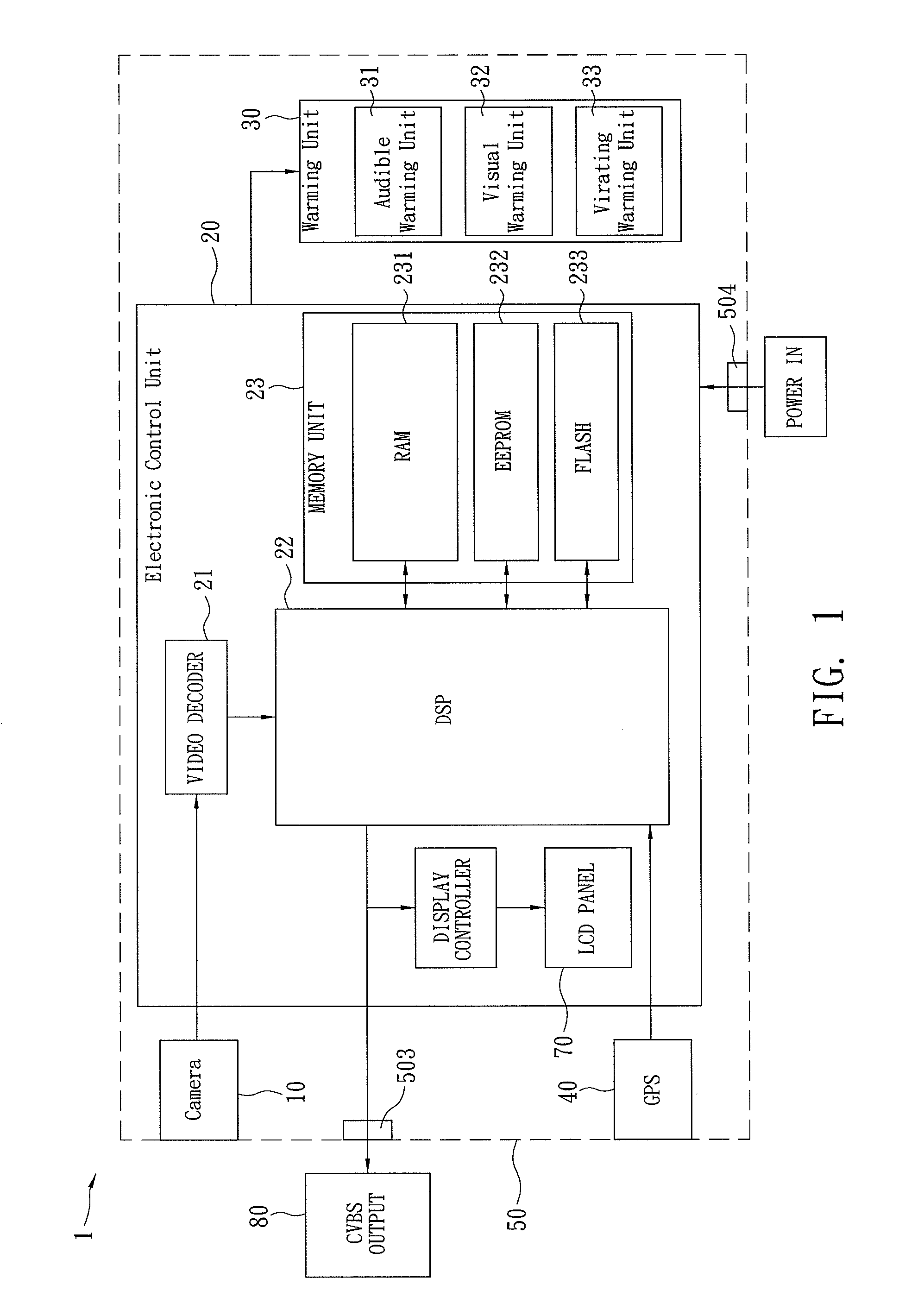
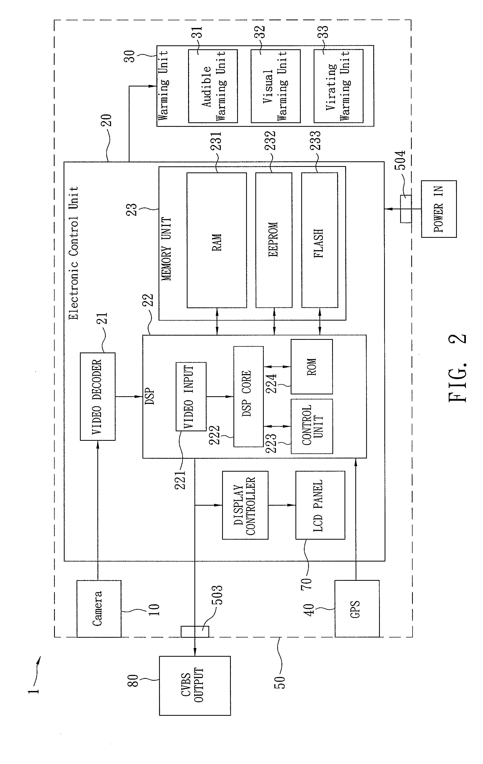
[0016]Refer to FIG. 1, a lane departure warning system (LDWS) 1 installed on vehicles according to the present invention includes a camera 10, an electronic control unit (ECU) 20, and at least one warning unit 30. The ECU 20 is further connected with a global positioning system (GPS) 40 so as to get vehicle speed signals of the car whenever the LDSW requires. In use, the camera 10 is used to track road images such as images of lane lines on freeways and send data of images to the ECU 20 for dealing with and recognizing images. The ECU 20 further obtains a vehicle-speed signal at that time by the connected GPS 40. Together with road images, the ECU 20 checks whether a dangerous driving happens. For example, when a car runs at the speed of 60 Km / hr or above on a highway, now the vehicle speed signal of 60 Km / hr is obtained by the GPS 40 and is input into the ECU 20 to be used as a criterion of (for) the LDWS 1 to send an alert. That means the LDWS 1 is preset to turn on the warning fu...


PUM


Abstract

A lane departure warning system (LDWS) installed on vehicles is revealed. The LDWS includes a camera that captures road images and the data of images is sent to an electronic control unit (ECU) for processing and recognition. The ECU is directly connected with a global positioning system (GPS) that provides vehicle speed signals so as to check whether dangerous driving occurs. Once the dangerous driving occurs, a warning unit is turned on to send an alert. The conventional LDWS that complicatedly connects with vehicles parts such as turn signal lights or speedometers is replaced by connection with a GPS. Thus the convenience of installation of LDWS in vehicles is improved.

Description

BACKGROUND OF THE INVENTION[0001]The present invention relates to a lane departure warning system (LDWS), especially to a lane departure warning system that connects with a global positioning system (GPS) for receiving vehicle speed signals so as to achieve the warning effect while vehicles departing the lane.[0002]As a popular transportation tool, cars are equipped with various electronics such as global positioning systems (GPS), lane departure warning systems (LDWS), or event data recorder (EDR) according to users' needs. The global positioning system (GPS) is a mature product in the market. In combination with a GPS receiver that receives information from GPS satellite to calculate users' own position in real time. Together with a preset electronic map and a display screen, users can know their positions, areas, directions and vehicle speed, accurately locate where they are and easily navigate to where they want to go.[0003]A conventional LDWS mainly includes a camera disposed i...

Claims


Application Information

Patent Timeline
Patent Type & Authority Applications(United States)
IPC IPC(8): H04N7/18
CPCB62D15/029
Inventor LO, CHIH-WEILIN, SHIH-HOWEI, HUI-CHEN
Owner CREATE ELECTRONICS OPTICAL
Why Eureka
Try Eureka