System and process for automated circuiting and branch circuit wiring

a branch circuit and wiring system technology, applied in the field of system and process for automated circuiting and branch circuit wiring, can solve the problems of fragmentation of an originally well-ordered circuit structure, laborious and inflexible known manual processes for producing complete electrical designs, and insufficient estimation of construction costs or actual construction of designs

Inactive Publication Date: 2012-08-30
DRAFTLOGIC SYST
View PDF6 Cites 26 Cited by
  • Summary
  • Abstract
  • Description
  • Claims
  • Application Information

AI Technical Summary

Benefits of technology

[0013]A design / drafting system or process for use by design professionals (also known as end users or client / engineers), is provided. The present system is capable of accepting or receiving end user or client input, including one or more electrical component designs (e.g. architectural drawing or building model having at least electrical components thereon) in digital format and, coupled with a rule-based process for applying standards and client preferences, generating a complete electrical design which may include: circuited electrical components, service device locations, service device interconnections, service device protection / conductor selection, branch circuit wiring, and various schedules related to each of these deliverables.

Problems solved by technology

The electrical components design does not, however, include circuiting and branch circuit wiring and is thus insufficient to either estimate construction costs or to actually construct the design.
Such known manual processes of producing complete electrical designs are laborious and inflexible.
Revisions can result in a fragmentation of an originally well-ordered circuit structure, with deletions and merely appending of newly revised circuits.
The impact of such revisions can result in further problems where a particular project is divided into a number of drawings that each must be updated manually.
The immense person hours expended creates two main disadvantages: a significant time delay from project start to completion, and a related increase in cost.
Further, while an architect, design professional or client is constrained by many known and standardized codes, there are also instances where the known codes are inapplicable and personal judgment must be applied.
Further, due to the difficulty involved in establishing the actual routing and specifications of conduit, wire, and cable (such routing and materials collectively referred to hereinafter as ‘wiring’), considering possible circuit grouping or routing options, it is a common practice in the industry to simply avoid illustrating wiring on the complete electrical design and to leave the actual routing of wiring to the field installers.

Method used


Image

  • System and process for automated circuiting and branch circuit wiring
  • System and process for automated circuiting and branch circuit wiring
  • System and process for automated circuiting and branch circuit wiring

Examples


example

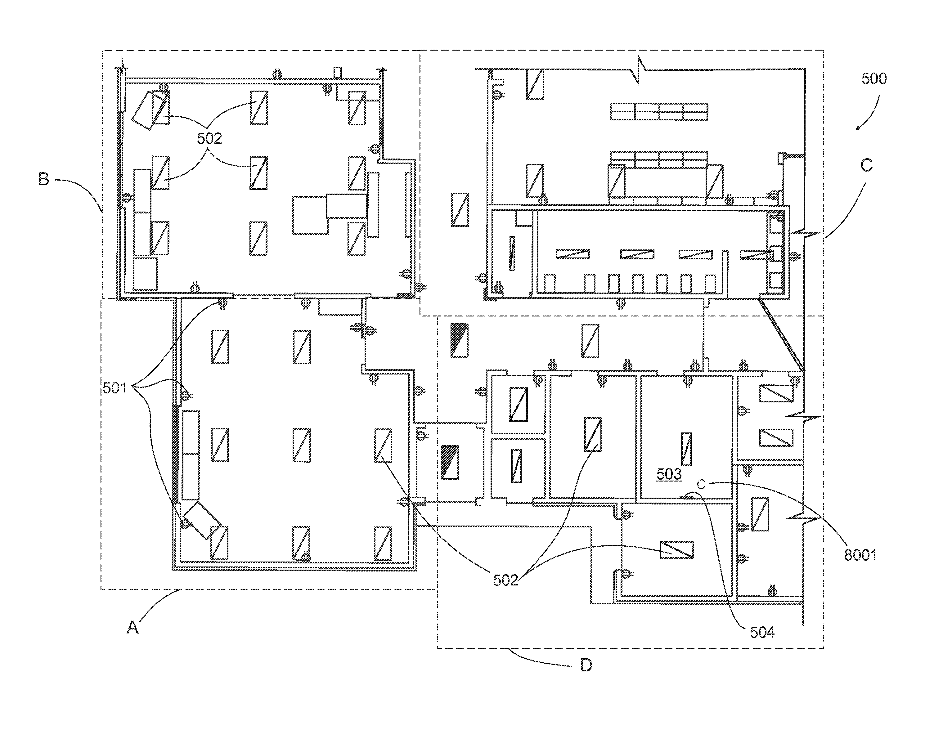
[0198]The process of the present system was applied during the design and construction of a one level school using the Canadian Electrical Code from among the various electrical codes supported by the present system. With reference FIGS. 5, and 6, the end user loaded an engineering drawing 500 having at least one electrical component and the appropriate set of parameters for a school in Canada was applied to the project.

[0199]In preparation for automated circuiting, the project is divided into service areas either by the user based on how they desire circuiting to service the electrical components; by the present system automatically through application of service area-pertinent: electrical standards, industry standard practice, and user parameters; or through a mix thereof. Each service area can further be divided into one or many subareas, by rooms for example. Service areas are also designated with a type so that automated circuiting knows whether to separate different component ...


PUM


Abstract

A system or process for providing complete electrical designs through: computer-automated circuiting; computer automated service device selection, placement, and interconnection; and computer-automated branch circuit wiring, wherein the complete electrical design complies with regulatory, industry standard practice, and client criteria.

Description

CROSS REFERENCE TO RELATED APPLICATIONS[0001]This is a continuation-in-part of application Ser. No. 12 / 626,612, filed Nov. 25, 2009.FIELD OF THE INVENTION[0002]The present system relates to a system for receiving an electrical components design, such as, for example a computer aided design (CAD) or building model comprising electrical systems, and creating a “complete electrical design” through computer-automated circuiting, computer automated service device selection-placement-interconnection, and computer-automated branch circuit wiring, wherein the complete electrical design complies with regulatory and client criteria.BACKGROUND OF THE INVENTION[0003]In the context of building design, architectural designs (building floor plans, CAD drawings and / or building model) comprise a multitude of elements or assets, such as corridors and rooms, all of which have different requirements for electrical and mechanical services. As such, architectural designs are provided to an engineer or de...

Claims


Application Information

Patent Timeline
Patent Type & Authority Applications(United States)
IPC IPC(8): G06F17/50
CPCG06F17/509G06F17/5004G06F30/13G06F30/18
Inventor WHITFORD, DEANSTEBNICKI, GERRYSMITH, TERRY
Owner DRAFTLOGIC SYST
Why Eureka
Try Eureka