
Method And System For Detecting And Locating By Reflectometry Electrical Faults In Metal Structures

a technology of reflectometry and electrical faults, applied in the direction of fault location by pulse reflection methods, instruments, transportation and packaging, etc., can solve the problems of significant effect on the value of the total resistance of the network, inability to carry out global detection, and inability to individually check the braids in an economic sens

Active Publication Date: 2012-09-06
AIRBUS OPERATIONS (SAS)
View PDF8 Cites 18 Cited by
  • Summary
  • Abstract
  • Description
  • Claims
  • Application Information

AI Technical Summary

Benefits of technology

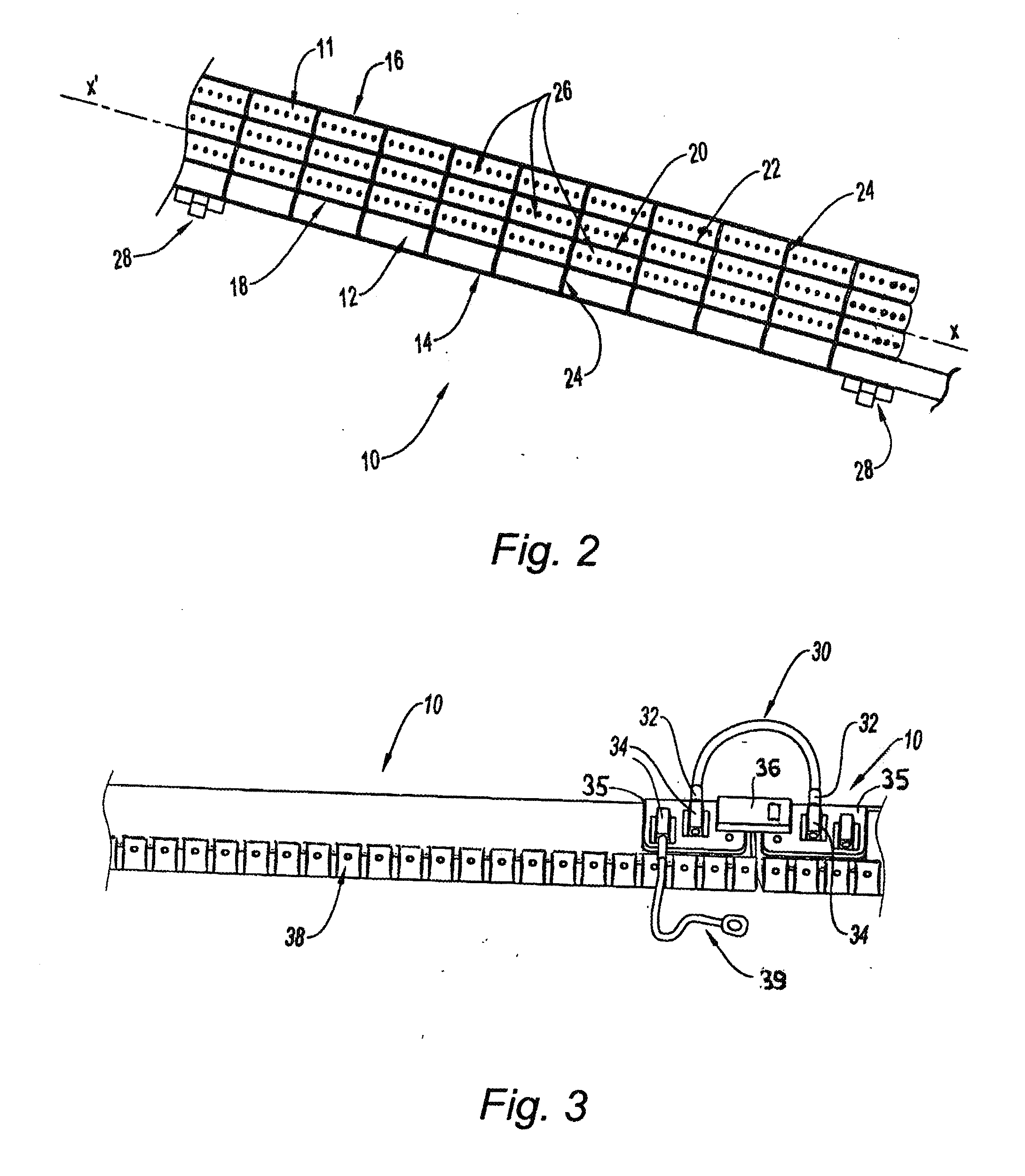
[0014]The invention relates also to a system for detecting and locating by reflectometry electrical faults in metal structures, able to implement the above-defined method. Such a system includes at least one insulated electrical conductor, held at a substantially constant distance from one of the walls of the said metal structure to be tested. The conductor is connected, at one of its ends, to means of transmission and injection of a probe signal and to means of connection to a device for detecting and analyzing a reflected signal and is in contact, at the other end, with the said metal structure.

Problems solved by technology

Specifically, the cable lengths represent several hundreds of kilometres in modern aeroplanes and reliable safety diagnostics of the electrical network is an important, even vital, issue.
This detection cannot be carried out globally by means of an ohmmeter since, because the raceways are connected to the network at many points, the loss or degradation of a braid does not have a significant effect on the value of the total resistance of the network.
An individual check of the braids is not realistic in an economic sense in view of their large number and their poor accessibility.
However, reflectometry does not provide for discriminating between signals reflected by circuit breaks or short-circuits and line impedance fluctuations that are also detected.

Method used


Image

  • Method And System For Detecting And Locating By Reflectometry Electrical Faults In Metal Structures
  • Method And System For Detecting And Locating By Reflectometry Electrical Faults In Metal Structures
  • Method And System For Detecting And Locating By Reflectometry Electrical Faults In Metal Structures

Examples


Embodiment Construction

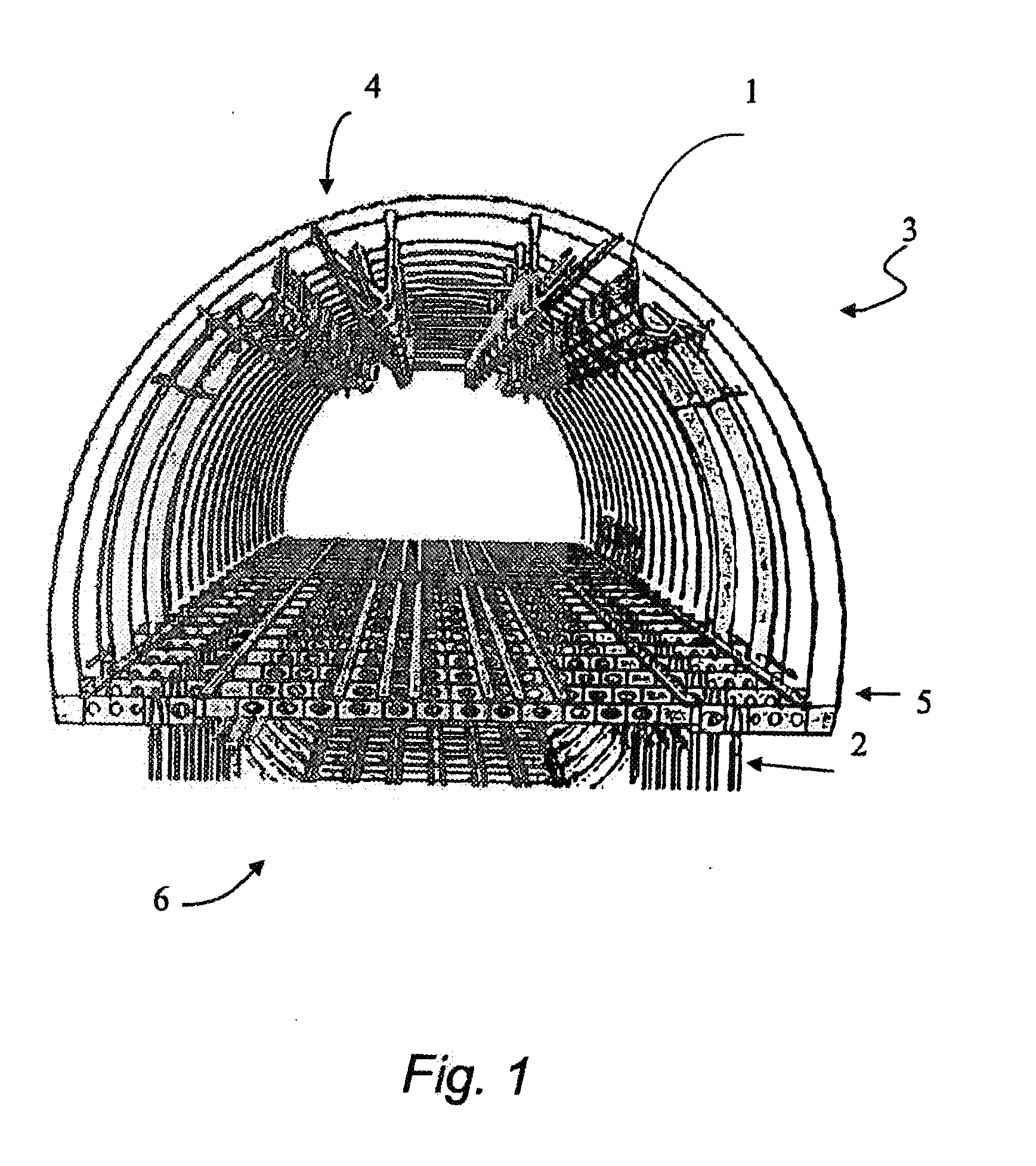
[0011]The invention aims to allow the application of this technology to the detection and locating of electrical faults in metal cable-support structures such as raceways, while providing for discriminating between reflected signals and impedance fluctuations. To this end, the invention proposes using a particular electrical propagation coupled to each raceway.

[0012]More specifically, an object of the invention is a method for detecting and locating electrical faults by reflectometry in metal cable-support raceway-type structures, in which an electrical propagation line is held at a substantially constant distance from each structure, the line being connected at one of the ends to the metal structure. At its other end, a probe signal is injected into the line and a reflected signal, in return from the injected signal, is detected and analyzed by comparison with a reference signature of an undisrupted reflected signal.

[0013]According to particular modes, the method operates in the fr...


PUM


Abstract

The invention aims to provide for detecting and locating by reflectometry electrical faults in a network of metal structures able to receive electrical cables and perform the return-current function of these cables. The invention consists in injecting a probe signal into a conductor, associated with the structures, then in analyzing the reflected signal by comparison with a reference signal.According to one example implementation, an insulated conducting element is held at a distance by fasteners fitted to supports secured to a wall of the metal structure.Application to raceways in composite-skin aeroplanes.

Description

TECHNICAL FIELD[0001]The invention relates to a method and a system for detecting and locating, by reflectometry, electrical faults in metal structures, in particular for the detection of inaccessible electrical anomalies, such as current flow faults or losses in an electrical conductor.[0002]A conventional anomaly is the return-current fault which in general is difficult to locate in electrical installations. Thus, in new aeroplanes with composite skins, such as carbon-fibre reinforced plastic materials (CFRPs), the skin can no longer perform the return-current function between the passengers and power sources, nor the electromagnetic protection, which functions were provided beforehand by the metal skin of the aeroplane.PRIOR ART[0003]To address this, networks of metal structures are proposed. These structures incorporate primary metal parts which generally receive several electrical cables. In particular, these parts form “U”-shaped or “I”-shaped metal structures to produce racew...

Claims


Application Information

Patent Timeline
Patent Type & Authority Applications(United States)
IPC IPC(8): G01R31/11
CPCB64F5/0045G01R31/11G01R31/008B64F5/60
Inventor LANDES, OLIVIERLOCHOT, CHRISTOPHE
Owner AIRBUS OPERATIONS (SAS)
Learn More