Vacuum valve

a vacuum valve and valve body technology, applied in the direction of air-break switches, high-tension/heavy-dress switches, electrical equipment, etc., can solve the problems of deterioration of interruption capability, damage or consumption of main electrodes, weakening of axial magnetic field, etc., to enhance interruption capability, enhance capability, and low cost

Active Publication Date: 2012-09-13
MITSUBISHI ELECTRIC CORP
View PDF7 Cites 2 Cited by
  • Summary
  • Abstract
  • Description
  • Claims
  • Application Information

AI Technical Summary

Benefits of technology

[0015]As has been described above, by controlling respective currents flowing through the plural the coil portions of the coil electrodes provided to the fixed contact and the movable contact on the rear surface side, the invention simultaneously achieves three objects: to make it possible to diffuse an arc homogeneously across the entire contact surfaces; to form no weak point portion in capability for withstanding high voltage in

Problems solved by technology

In the vacuum interrupter that enhances an interruption capability by generating an axial magnetic field, an eddy current is induced at the disc-shaped contact and there is a problem that a field generated by the eddy current weak

Method used


Image

  • Vacuum valve
  • Vacuum valve
  • Vacuum valve

Examples


first embodiment

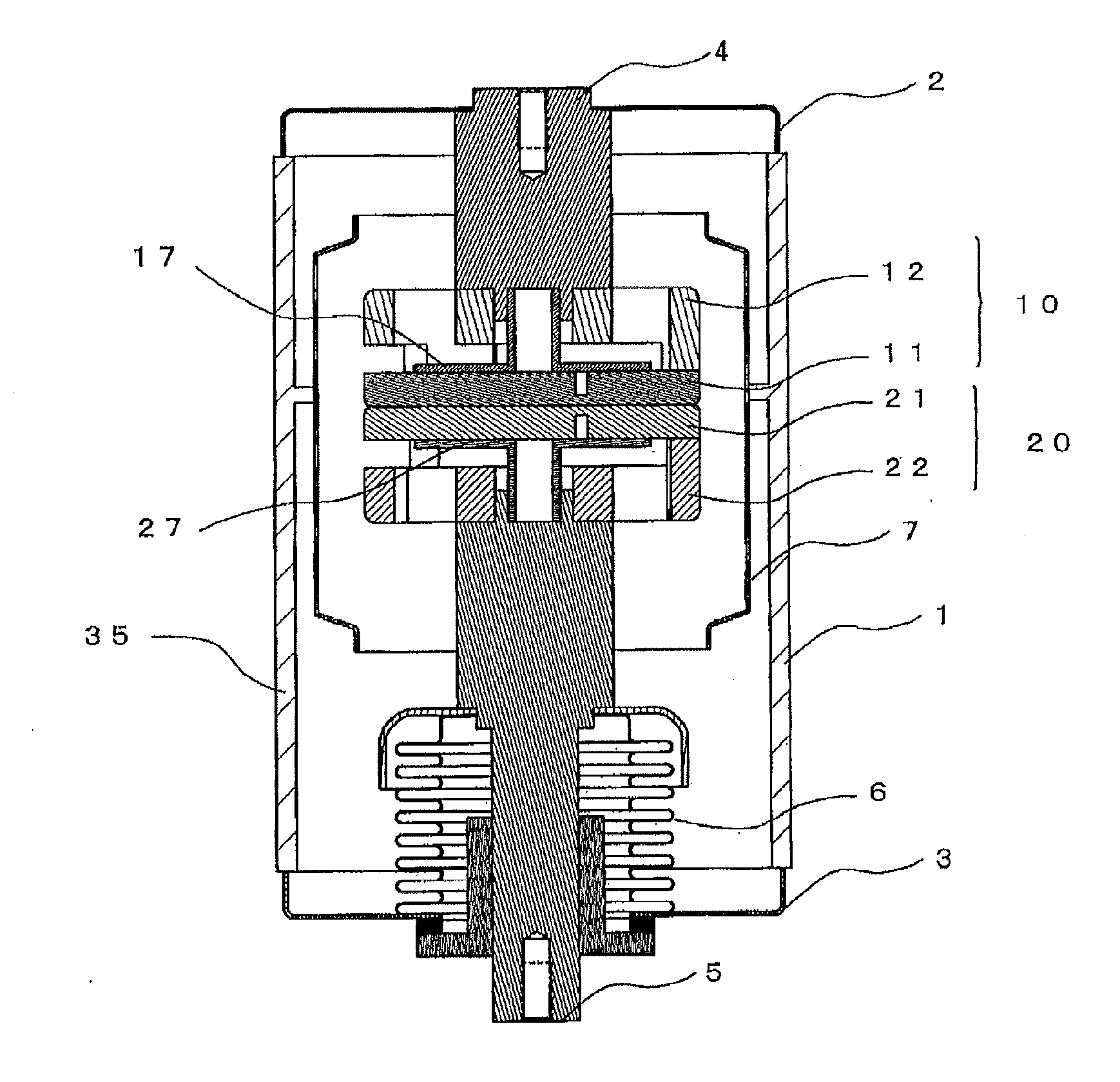
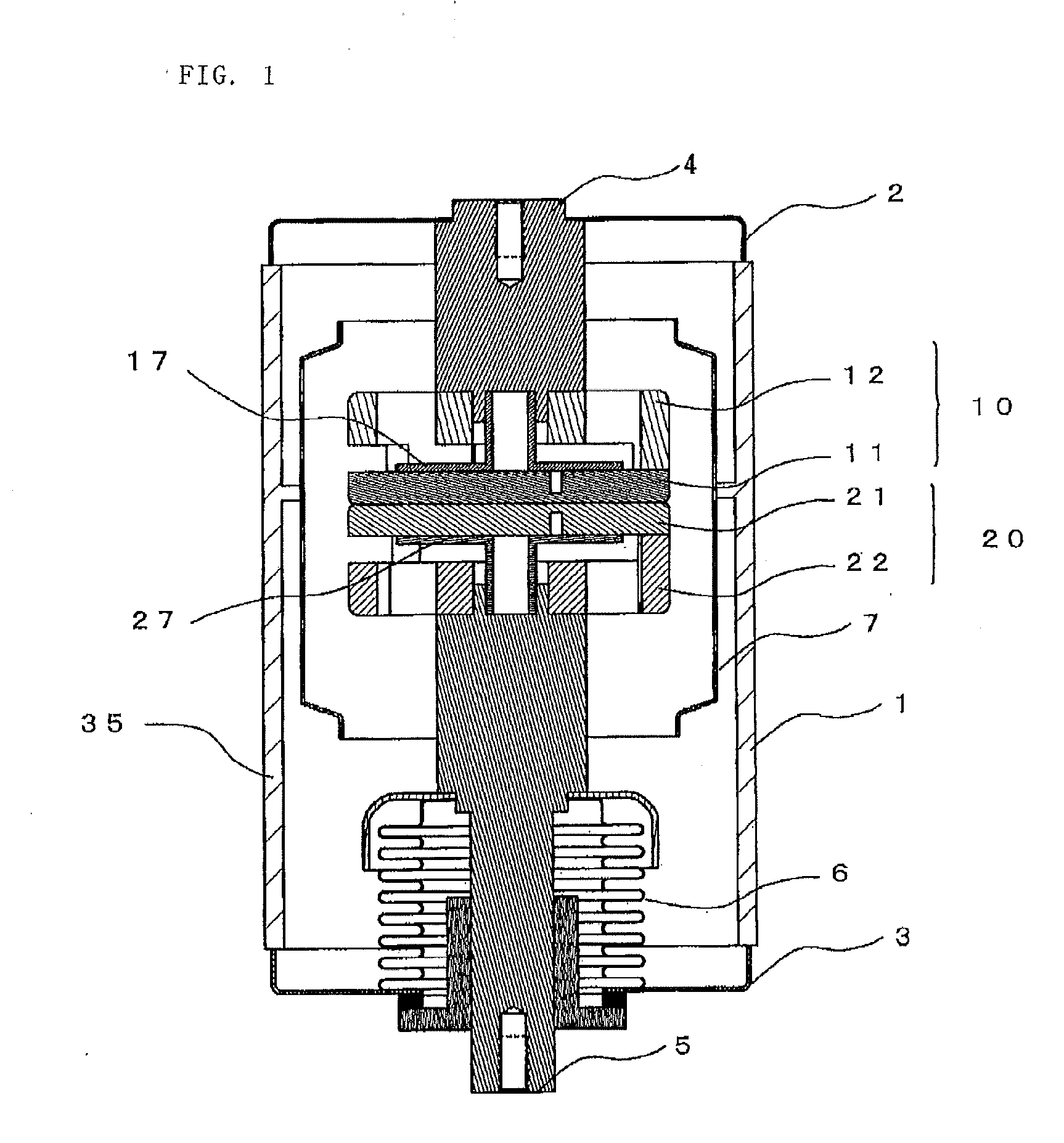
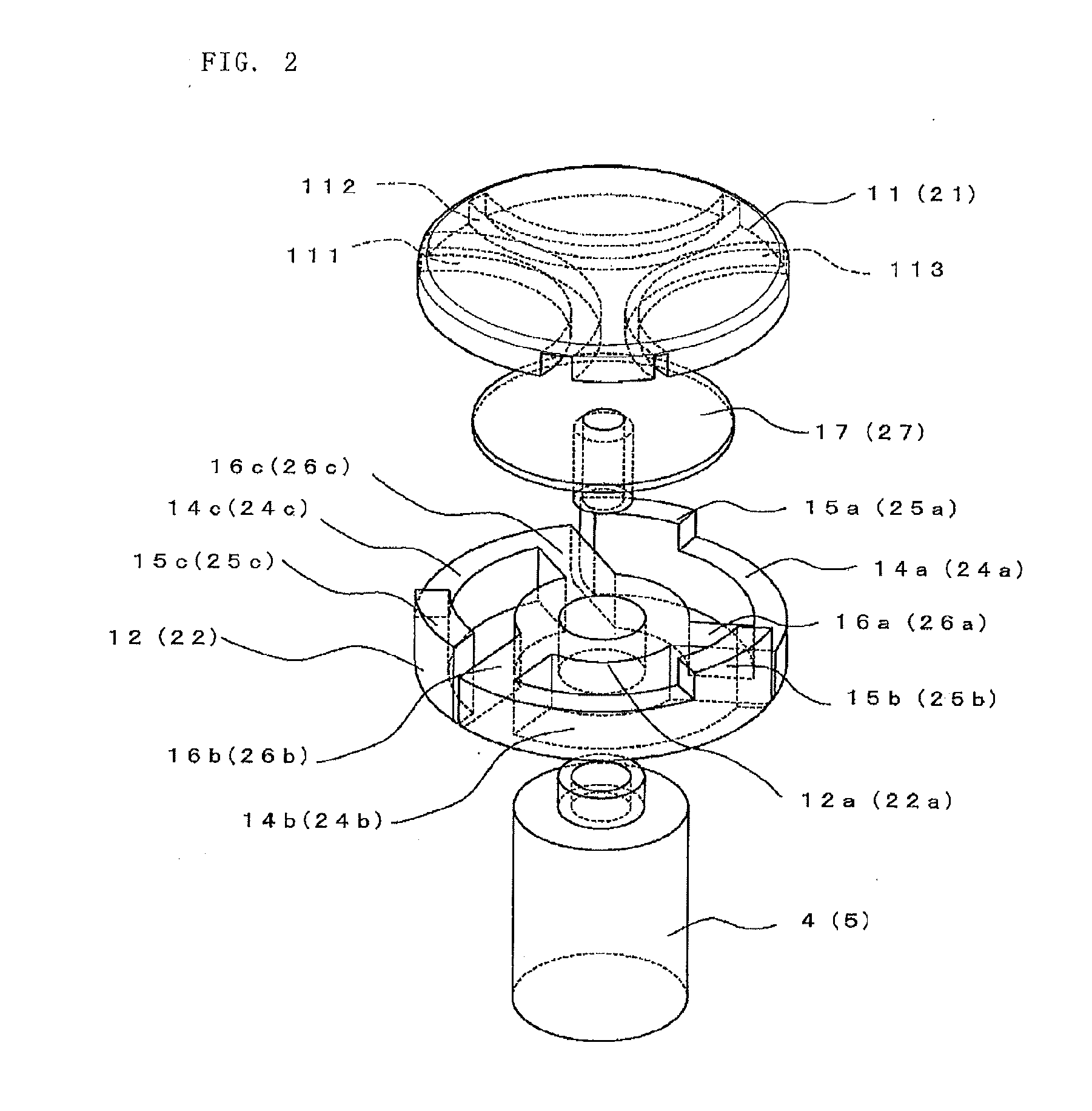
[0024]FIG. 1 is a cross section of a vacuum interrupter of a first embodiment. FIG. 2 is an exploded perspective view used to describe a configuration of a fixed electrode of the first embodiment . FIG. 3 is a plan view of a fixed contact of the first embodiment. Referring to the drawings, a vacuum interrupter 35 of the invention includes an insulating cylinder 1 made of alumina ceramic or the like, a fixed-side end plate 2 covering one end opening portion of the insulating cylinder 1, and a movable-side endplate 3 covering the other end opening portion of the insulting cylinder 1, and forms a vacuum container. The fixed-side and movable-side end plates 2 and 3 are attached to respective end faces of the insulting cylinder 1 by brazing. A fixed electrode bar 4 is joined to the fixed-side end plate 2 at a center portion by brazing and a fixed electrode 10 is joined to a tip end of the fixed electrode bar 4 by brazing. A movable electrode 20 is provided oppositely to the fixed electro...

second embodiment

[0035]FIG. 4 is a plan view of a fixed contact of a vacuum interrupter of a second embodiment. Because the vacuum interrupter is of the same configuration as the counterpart of the first embodiment above, a description thereof is omitted and a description will be given to a fixed contact (movable contact) alone herein. As is shown in FIG. 4, grooves 111A, 112, and 113 are provided to a rear surface of a fixed contact 11 (movable contact 21) so as to surround joint portions to a fixed coil electrode 12 (movable coil electrode 22). The joint portions referred to herein mean portions in which connection portions 15 (25) of the fixed coil electrode 12 (22) and the fixed contact 11 (21) are joined to each other. Also, the grooves 111A, 112, and 113 are of a shape that does not penetrate through the fixed contact 11 (21). The groove 111A is formed of grooves in two rows parallel to each other at a predetermined interval. Each of the grooves 112 and 113 is a single-row groove, and a groove...

third embodiment

[0039]FIG. 5 is a plan view of a fixed contact of a vacuum interrupter of a third embodiment. Because the vacuum interrupter is of the same configuration as the counterpart of the first embodiment above, a description thereof is omitted and a description will be given to a fixed contact (movable contact) alone herein. Arc-shaped grooves 112 and 113 are provided to the rear surface of the fixed contact 11 (21) so as to surround joint portions to a fixed coil electrode 12 (22). Further, a joint portion at another point is provided to a thin portion 120 obtained by making the rear surface of the fixed contact 11 (21) thin from a periphery along an arc-shaped outline. The joint portions referred to herein mean portions in which connection portions 15 (25) of the fixed coil electrode 12 (22) and the fixed contact 11 (21) are joined to each other. A connection portion 15c (25c) joined to the thin portion 120 is formed to protrude more than the other two connection portions 15a and 15b (25...


PUM


Abstract

A fixed electrode 10 and a movable electrode have coil electrodes formed of plural coil portions installed at both contacts and on a rear surface side in a divided manner in a circumferential direction along peripheries of the contacts such that a longitudinal field is generated in a direction in which the fixed contact and the movable contact come close to and move apart from each other. Protruding portions joined to the contacts are provided to tip ends of the respective coil portions to form joint portions to the respective contacts. A current to be flowed is controlled by changing resistance values between the contacts and the coil electrodes for each joint portion.

Description

TECHNICAL FIELD[0001]The present invention relates to a vacuum interrupter configured to diffuse an arc using a field generated by a current flowing through electrodes.BACKGROUND ART[0002]FIG. 8 is a conceptual view showing a configuration of a typical breaker provided with a vacuum interrupter 35. A breaker 30 is provided with an insulating frame 34 housing therein the vacuum interrupter 35 and installed on a carriage 31. The vacuum interrupter 35 has a fixed-side connection conductor 36 connected to a fixed electrode bar, a flexible conductor 37 connected to a movable electrode bar, and a movable-side connection conductor 38. The fixed-side connection conductor 36 and the movable-side connection conductor 38 are introduced to an outside of the insulating frame 34. Installed at a front of the carriage 31 are a face plate 32 and an operation mechanism 33.[0003]A vacuum interrupter adopted in such a breaker includes a bottomed cylindrical vacuum container made of an insulating materi...

Claims


Application Information

Patent Timeline
IPC IPC(8): H01H33/66
CPCH01H33/6644H01H33/6642H01H33/664
Inventor HARADA, TAKAKAZUITOTANI, TAKAYUKI
Owner MITSUBISHI ELECTRIC CORP
Why Eureka
Try Eureka