Battery pack for electric power tool, and battery connection device

a technology for electric power tools and battery packs, which is applied in the direction of digital transmission, exchanging data chargers, transportation and packaging, etc., can solve the problems of abnormal heat generation in the battery packs, damage to the battery connection devices, etc., and achieve the effect of reducing the storage capacity of the battery packs

Active Publication Date: 2012-09-20
MAKITA CORP
View PDF2 Cites 25 Cited by
  • Summary
  • Abstract
  • Description
  • Claims
  • Application Information

AI Technical Summary

Benefits of technology

[0026]In addition, the battery pack can perform each of the first conversion and second conversion using one fixed formula, Thereby, storage capacity of the battery pack can be lower than if a plurality of types of formulas for each of the first and second conversions are stored and one formula is chosen therefrom to perform each of the first and second conversions,

Problems solved by technology

When such inauthentic battery packs are connected to the battery connection devices, there is a risk of damage to the battery connection devices or generation of abnormal heat in the battery packs.

Method used


Image

  • Battery pack for electric power tool, and battery connection device
  • Battery pack for electric power tool, and battery connection device
  • Battery pack for electric power tool, and battery connection device

Examples


first embodiment

[0039](Overall Configuration)

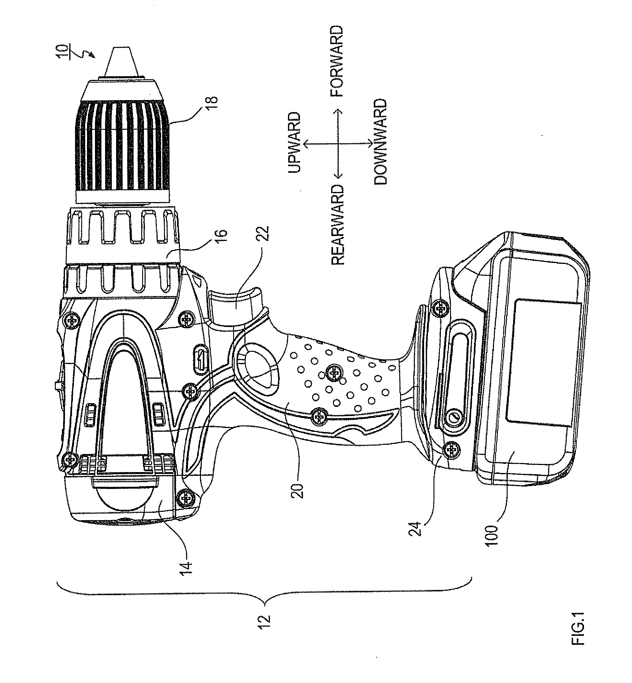
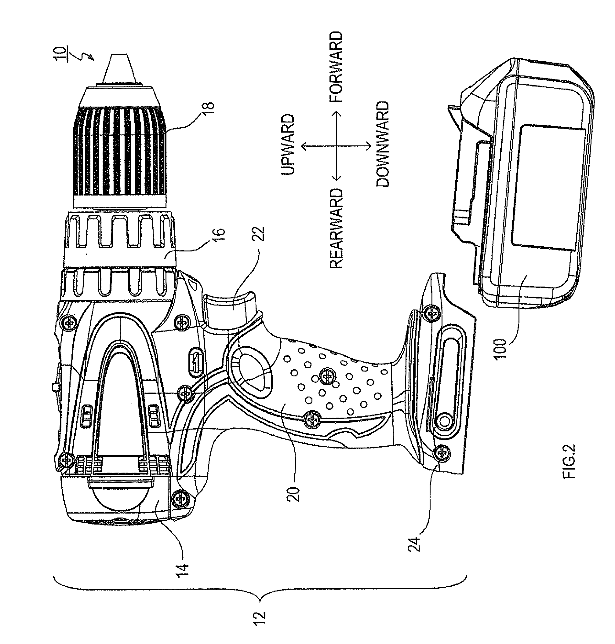
[0040]FIG. 1 is a side view of a driver drill to which the present invention is applied.

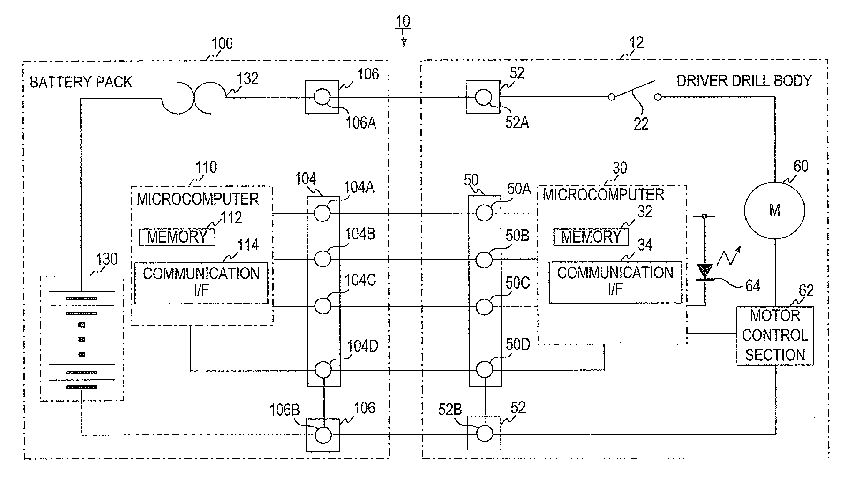
[0041]As shown in FIG. 1, a driver drill body 12 of the driver drill 10 includes a motor housing 14, a gear housing 16 located in front of the motor housing 14, a drill chuck 18 located in front of the gear housing 16, and a hand grip 20 located below the motor housing 14.

[0042]The motor housing 14 houses a motor 60 (see FIG. 4; not shown in FIG. 1) that generates a drive force for rotatably driving the drill chuck 18.

[0043]The gear housing 16 houses a gear mechanism (not shown) that transmits the drive force of the motor 60 to the drill chuck 18.

[0044]The drill chuck 18 is provided with a connection mechanism (not shown) that detachably connects a tool bit (not shown) to a front end portion of the drill chuck 18.

[0045]The hand grip 20 is formed into a shape such that an operator of the driver drill 10 can hold the hand grip 20 with one hand. In front at the top of th...

second embodiment

[0115]The second embodiment of the present invention will be explained based on FIG. 7.

[0116](Authentication Routine 2)

[0117]FIG. 7 shows an authentication routine 2 which is performed by the microcomputer 110 of the battery pack 100 and the microcomputer 210 of the charging device 200 instead of the authentication routine 1 in FIG. 6 described above. The authentication routine on the charging device 200 side is shown in S420 to S442. The authentication routine on the battery pack 100 side is shown in S510 to S532.

[0118]Signs A1, B1, C1, D1, E1, X1 and Y1 in S420 to S442 and S510 to S532 in FIG. 7 correspond to signs A, B, C, D, E, X and Y in FIG. 6. The aforementioned description on the signs A, B, C, D, E, X and Y in FIG. 6 should be also referenced with regard to the signs A1, B1, C1, D1, E1, X1 and Y1 in FIG. 7.

[0119]In addition, the microcomputers 110 and 210 start this process when detecting, based on the aforementioned temperature signal and communication signal, that the bat...

third embodiment

[0140]A third embodiment of the present invention will be explained based on FIG. 8.

[0141]As shown in FIG. 8, an adapter 302 may be used for charging a battery pack 300 by a charging device 304. The adapter 302 is provided with a discharge circuit to forcibly discharge the battery pack 300 to be refreshed when the battery pack 300 is charged.

[0142]The battery pack 300 stores a refresh necessity flag which is set based on the number of charging times since the last refresh, for example. The adapter 302, when the battery pack 300 is attached as shown in FIG. 8, reads the refresh necessity flag stored in the battery pack 300.

[0143]The adapter 302, based on the necessity refresh flag, forces the battery pack 300 to discharge electricity by the discharge circuit of the adapter 302 for refresh if needed. On the other hand, the adapter 302, based on the necessity refresh flag read out from the battery pack 300, connects the battery pack 300 to the charging circuit of the charging device 30...


PUM


Abstract

A battery connection device is provided with an authentication data creating unit that creates authentication data, a conversion unit that performs a first conversion of the authentication data, a transmission unit that transmits the authentication data to a battery pack, a receiving unit that receives from the battery pack a battery-side conversion result that is data obtained after the authentication data is converted by the battery pack, a reverse conversion unit that, on an assumption that the battery pack creates the battery-side conversion result by performing the first conversion and a second conversion on the authentication data, performs a reverse conversion of the second conversion on the battery-side conversion result, and a determination unit that determines whether or not the battery pack is an authentic product by comparing a result of the reverse conversion with a result of the first conversion.

Description

CROSS-REFERENCE TO RELATED APPLICATIONS[0001]This international application claims priority from Japanese Patent Application No. 2009-295265 filed on Dec. 25, 2009 in the Japan Patent Office, the entire disclosure of which is incorporated herein by reference.TECHNICAL FIELD[0002]The present invention relates to a battery pack for electric power tool, and a battery connection device that electrically connects with the battery pack for electric power tool.BACKGROUND ART[0003]Conventionally, there are electronic devices known as battery connection devices which electrically connect with a battery pack for electric power tool. Such electronic devices include a charging device for charging the battery pack, an electric power tool to which electric power is supplied from the battery pack for electric power tool, and a radio to which electric power is supplied from the battery pack for electric power tool.[0004]Other than authentic battery packs manufactured by official manufacturers, inau...

Claims


Application Information

Patent Timeline
Patent Type & Authority Applications(United States)
IPC IPC(8): H02J7/00
CPCH02J7/00H04L9/3271H02J2007/0001G06F21/44H02J7/00036H02J7/00045H02J7/00047
Inventor OKABAYASHI, HISAKAZUNODA, MASAFUMI
Owner MAKITA CORP
Why Eureka
Try Eureka