Display control apparatus

a control apparatus and display technology, applied in the field of display control apparatus, can solve the problems of inability to accurately detect low illumination of approximately 5, and inability of light sensor to accurately detect illuminance exceeding 100 lx, so as to achieve accurate and speedy acquisition of information about illuminance by external light, accurate and speedy

Inactive Publication Date: 2012-09-20
FUJITSU GENERAL LTD
View PDF1 Cites 7 Cited by
  • Summary
  • Abstract
  • Description
  • Claims
  • Application Information

AI Technical Summary

Benefits of technology

[0016]When one control to be performed is chosen, based on the illuminance by the external light, from amongst the first control for the case where the illuminance by the external light is relatively high and the second control for the case where the illuminance by the external light is relatively low, the information about the illuminance by the external ...

Problems solved by technology

However, when an adopted relatively-low sensitivity light sensor is operable to detect illuminance in a range, for example, from 0 lx to 100,000 lx and indicates a detection result in 8 bits (0 to 255), the sensor cannot accurately detect low illuminance of approximately 5 lx because a resolution is too low.
On the other hand, when an adopted relatively-high sensitivity light sensor is operable to detect illuminance in a range, for example, from 0 lx to 100 lx, the sensor cannot accurately detect illuminance exceeding 100 lx because the ...

Method used


Image

  • Display control apparatus
  • Display control apparatus
  • Display control apparatus

Examples


first embodiment

[0035]

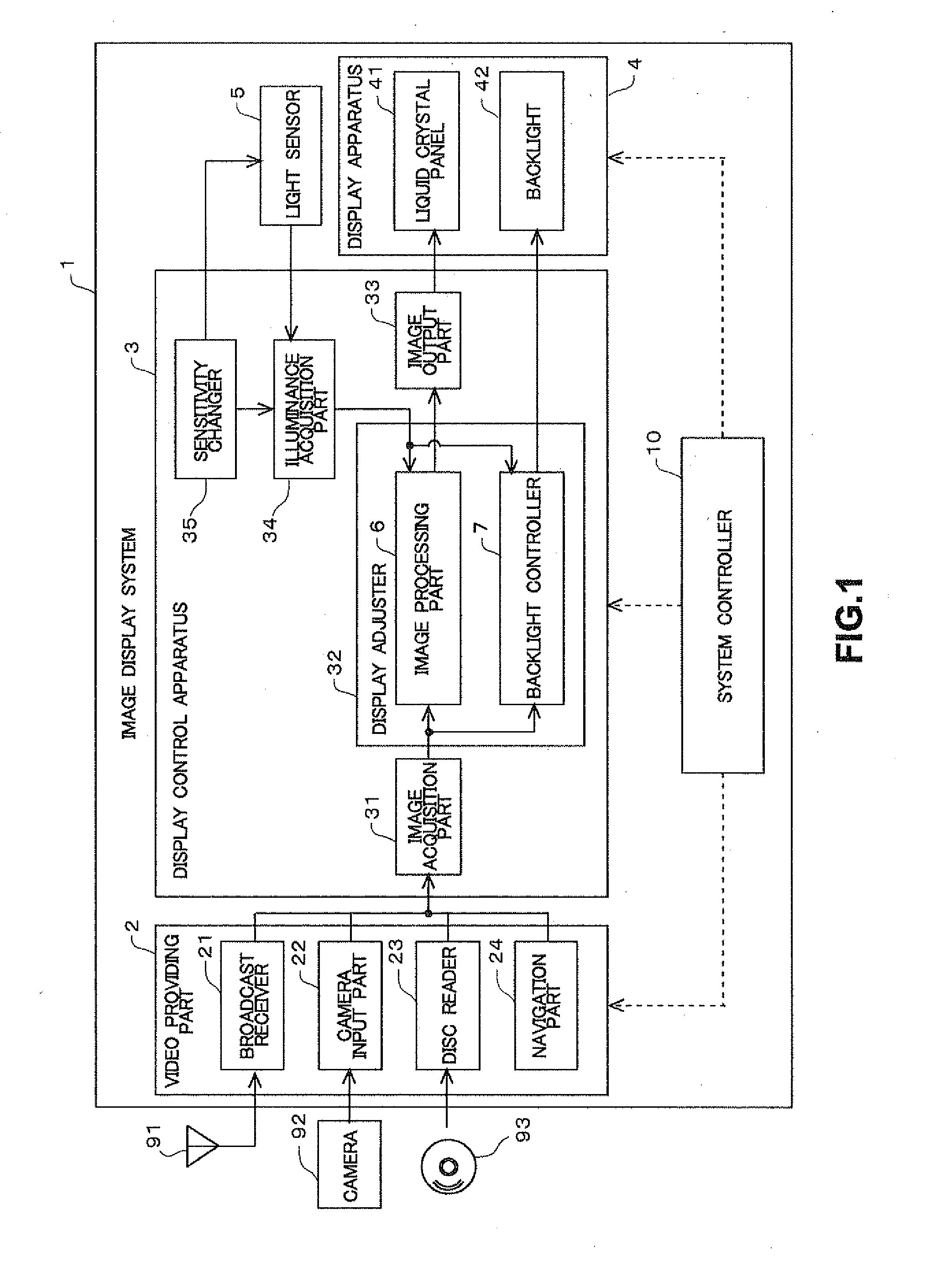
[0036]FIG. 1 is a block diagram illustrating a configuration of an image display system 1 in this embodiment. A navigation system for a vehicle, such as a car, is an example of the image display system 1. The image display system 1 for installation in a vehicle has a function of displaying various types of information for a user in a cabin of the vehicle.

[0037]As shown in FIG. 1, the image display system 1 includes a display apparatus 4 that displays various images, a display control apparatus 3 that controls a display of the display apparatus 4, and a video providing part 2 that provides an image to be displayed on the display apparatus 4.

[0038]The image display system 1 further includes a system controller 10 that controls the entire image display system 1. The system controller 10 is a microcomputer composed of, for example, a CPU, a RAM, a ROM and the like. Various control functions of controlling the entire system are implemented by arithmetic processing performed by the ...

second embodiment

2. Second Embodiment

[0103]Next, a second embodiment is described. A configuration and a process of an image display system 1 in the second embodiment are substantially the same as the image display system 1 in the first embodiment. Therefore, points different from the first embodiment are hereinafter mainly described. In the first embodiment, the ratio of the low sensitivity period PL to the high sensitivity period PH in the cycle P is fixed at 5:5 (refer to FIG. 7). On the other hand, in the second embodiment, a ratio of a low sensitivity period PL to a high sensitivity period PH in a cycle P is changed.

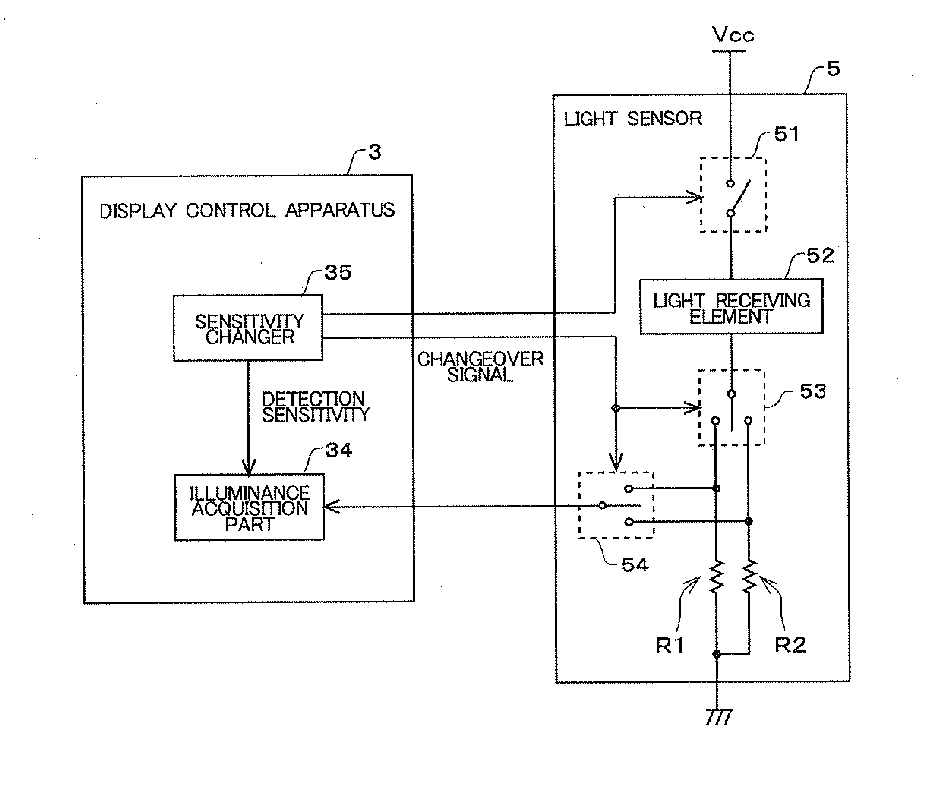
[0104]FIG. 11 illustrates a configuration, of the image display system 1, relating to acquiring illuminance by external light in the second embodiment. A display control apparatus 3 in the second embodiment further includes a ratio changer 36 in addition to the configuration of the display control apparatus 3 (refer to FIG. 3) in the first embodiment. The ratio changer 36 changes th...


PUM


Abstract

An image display system includes a light sensor operable to change a detection sensitivity. The light sensor outputs a signal according to an intensity of external light exerting an influence on a screen of a display apparatus and to the detection sensitivity. An illuminance acquisition part of a display control apparatus acquires illuminance by the external light based on the signal output from the light sensor. Moreover, a display adjuster adjusts a displaying state of the display apparatus in accordance with the illuminance by the external light acquired by the illuminance acquisition part. A sensitivity changer periodically alternates between a “low sensitivity” of the detection sensitivity and a “high sensitivity” of the detection sensitivity of the light sensor. Thus, even when changing significantly, the illuminance by the external light can be accurately and speedily acquired.

Description

BACKGROUND OF THE INVENTION[0001]1. Field of the Invention[0002]The invention relates to control relating to display of a display apparatus.[0003]2. Description of the Background Art[0004]When external light is incident on a display of a display apparatus, visibility of the display apparatus may be reduced depending on illuminance by the external light. Therefore, various technologies have been conventionally proposed to adjust a displaying state of the display apparatus in accordance with the illuminance by the external light.[0005]For example, when the external light is dark like at night, a screen of the display apparatus is too bright for a user because the screen is much brighter as compared to surrounding environment, and the visibility of the screen of the display apparatus is reduced. Therefore, a technology that reduces an amount of light (light amount) of a backlight of the display apparatus when the illuminance by the external light is relatively low, in accordance with t...

Claims


Application Information

Patent Timeline
IPC IPC(8): G06F3/038
CPCG09G3/3611G09G2360/144G09G2320/0666G09G2320/0626
Inventor TANAKA, TOSHIO
Owner FUJITSU GENERAL LTD
Why Eureka
Try Eureka