

Fiber optic rotary joint
a technology of fiber optics and rotary joints, applied in the direction of optics, instruments, optical light guides, etc., can solve the problems of optical fiber communication, inability or practical to rotate or centerline, width distortion, etc., to achieve the effect of reducing mechanical tolerance, reducing cross-talk, and sufficient signal strength
- Summary
- Abstract
- Description
- Claims
- Application Information
AI Technical Summary
Benefits of technology
Problems solved by technology
Method used
Image

Examples
Embodiment Construction
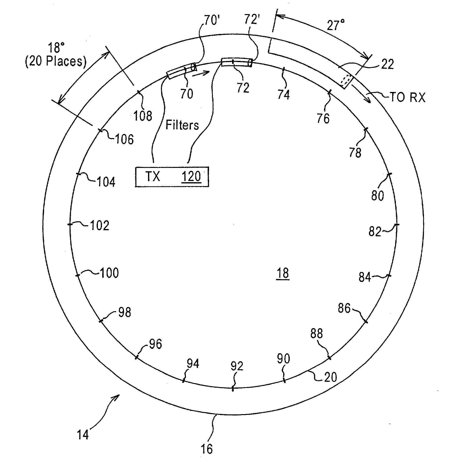
[0025] Refer now to FIGS. 1 and 2 where a first embodiment of a fiber optic rotary joint, generally indicated at 14, constructed in accordance with the principles of the present invention, is shown. The fiber optic joint 14 is usable in any environment requiring large diameter capable of transmitting high bit-rate signals and is particularly useful for cat-scan machines. For convenience, the fiber optic rotary joint will be described in relation to the orientation illustrated in FIG. 1 and consequently terms such as "above," "upwardly," and "clockwise," and "counterclockwise," as used herein are to be construed in the relative, rather than absolute sense. It is anticipated that those of ordinary skill in this art will appreciate that the apparatus of this invention may be oriented an any position that will suit any specific use.
[0026] The depicted fiber optic rotary joint 14 includes a stator 16 and a rotor 18. Rotor 18 has a circular outer circumference 20. Stator 16 includes a wav...
PUM
 Abstract
Description
Claims
Application Information