Paper printing method for a line printer, and a line printer
a printing method and line printer technology, applied in the direction of typewriters, printing, spacing mechanisms, etc., can solve the problems of increasing the size and cost of the line printer, affecting the printing quality of the paper, etc., and achieve the effect of reducing cost and making the paper smaller and more compa
- Summary
- Abstract
- Description
- Claims
- Application Information
AI Technical Summary
Benefits of technology
Problems solved by technology
Method used
Image

Examples
first embodiment
of a Label Printing Operation
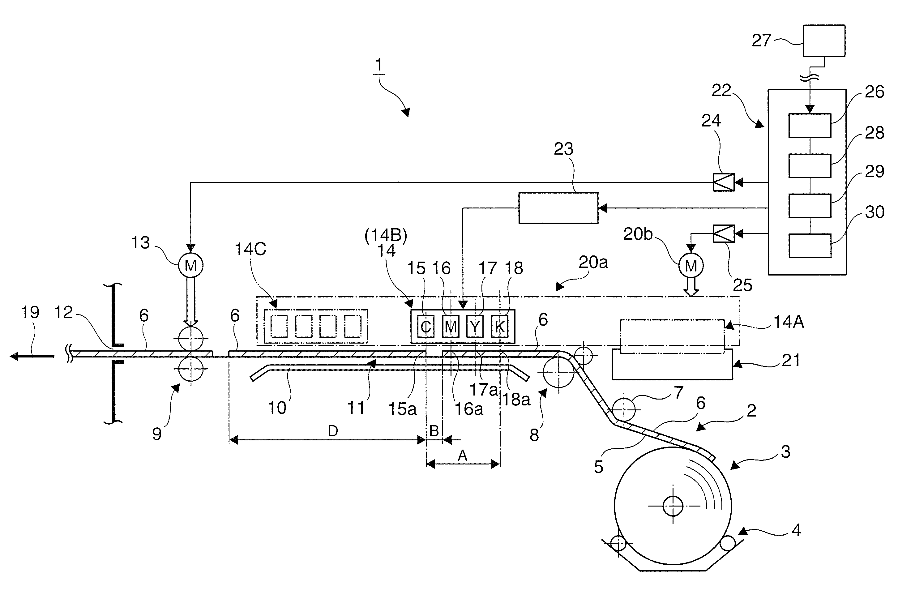
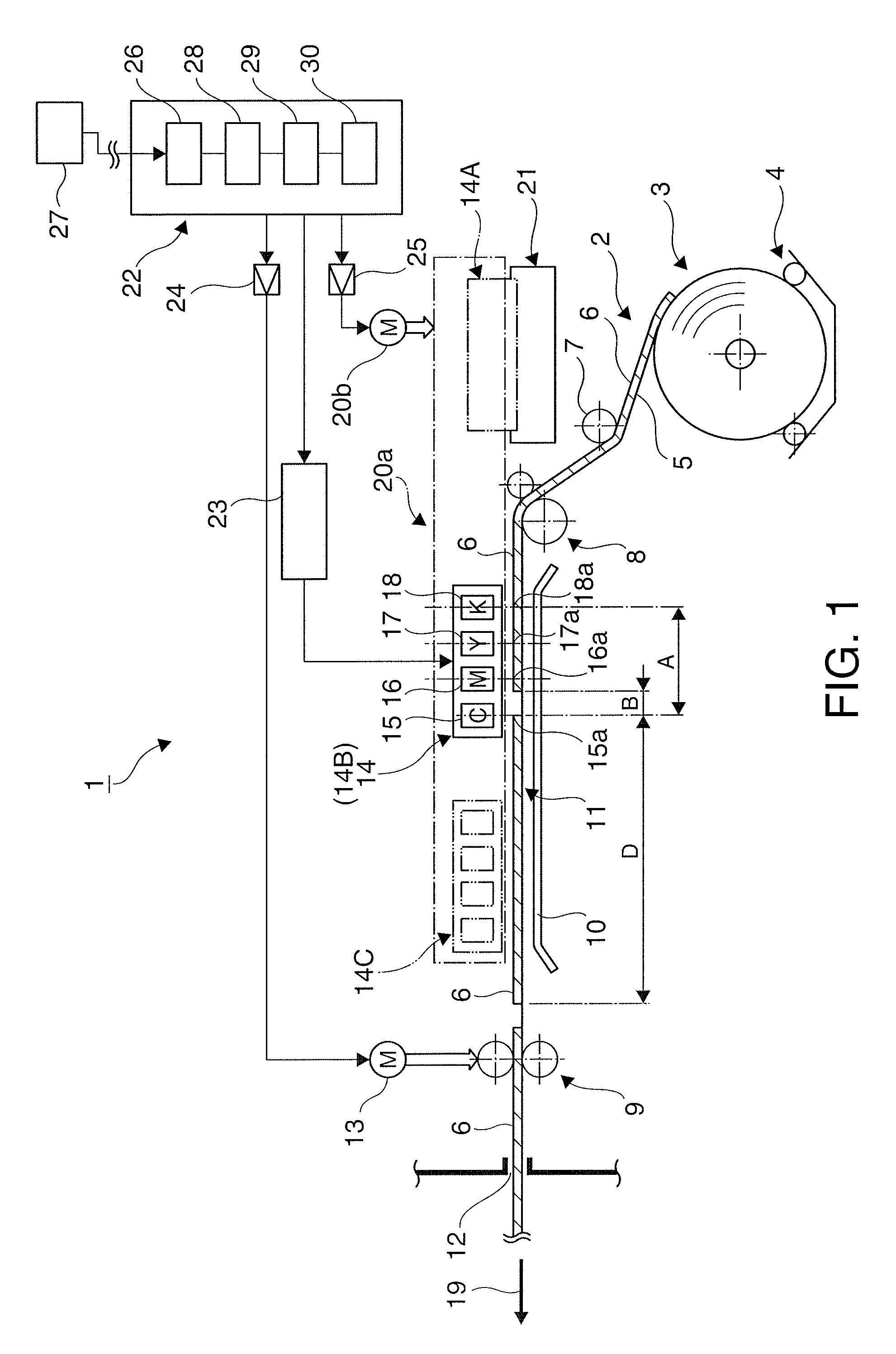
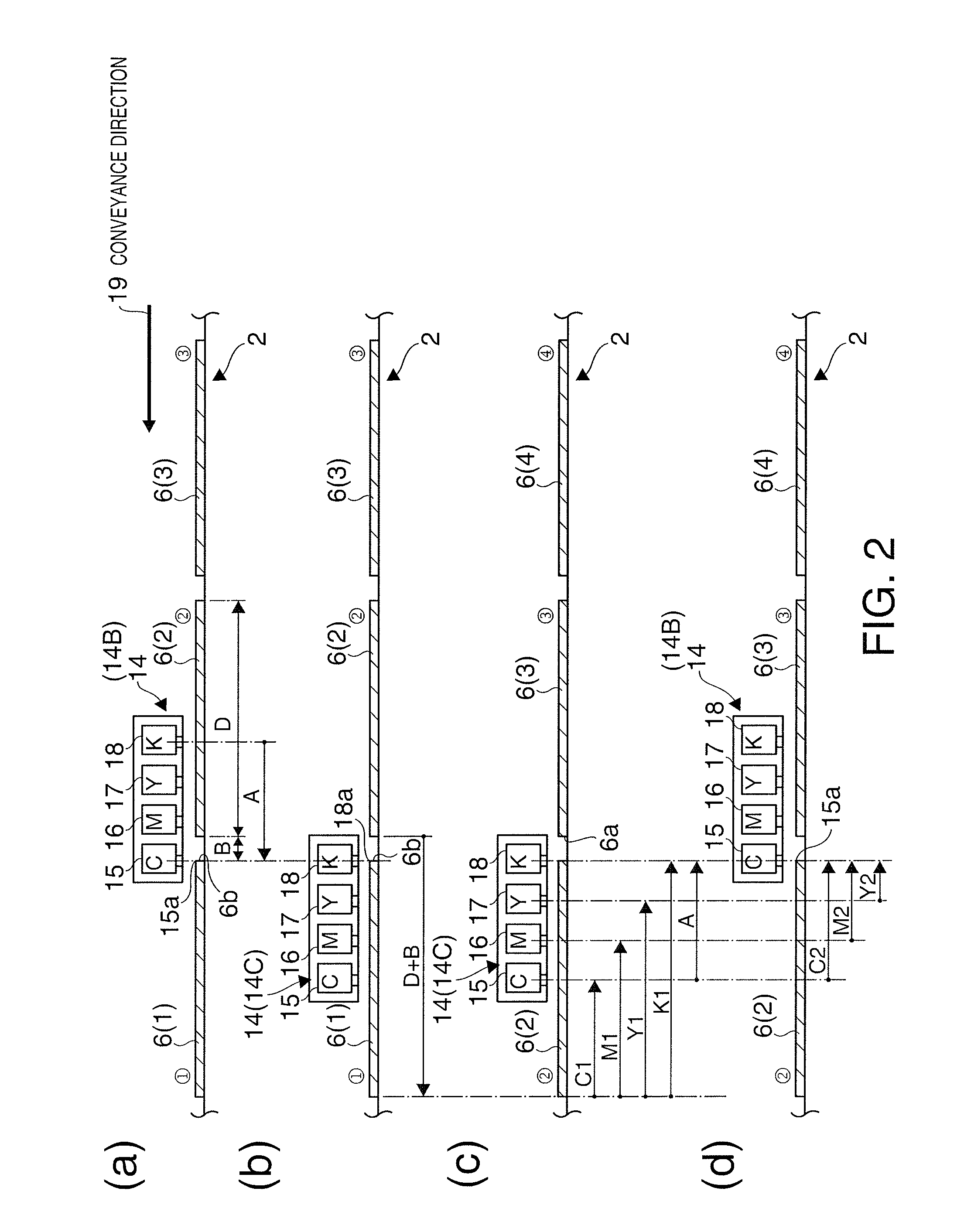
[0040]FIG. 2 describes the label printing operation of the line printer 1 according to a second embodiment of the invention. When the label paper 2 is set in the conveyance path 11 in this example, the label paper 2 is positioned so that the trailing end 6b (end-of-printing position) of the label 6(1) preceding (on the downstream side of in the conveyance direction) the label 6(2) to be printed is set to the printing position 15a of the first inkjet line head 15 of the head unit 14 at the first position 14B as shown in FIG. 2 (a). Note that in the initial standby position the head unit 14 is set to the maintenance position 14A opposite the maintenance unit 21.
[0041]When a print command for the label 6(2) is then received, the control unit 22 moves the head unit 14 from the first position 14B to the second position 14C (printhead moving step). This second position 14C is set so that the printing position 18a of the last inkjet line head 18 in the head uni...
second embodiment
of a Label Printing Operation
[0050]When printing on label 6(2) in the first embodiment described above, the label paper 2 is first fed in the conveyance direction 19 (forward) while the head unit 14 remains at the first position 14B. However, printing while first moving the head unit 14 is also possible.
[0051]FIG. 3 describes this label printing operation.
[0052]In this case as shown in FIG. 3 (a), the head unit 14 starts at the first position 14B (the end-of-printing position of label 6(1)), and the head unit 14 is then moved distance A in the conveyance direction 19 to the second position 14C as shown in FIG. 3 (b).
[0053]In the next print step, the label 6(2) is printed while moving the head unit 14 distance A from the second position 14C to the first position 14B. As a result, as shown in FIG. 3 (c), black ink K, yellow ink Y, and magenta ink M are printed from the leading end 6a to the trailing end 6b of the label 6(2) in the areas indicated by arrows K1, Y1, and M1.
[0054]The rem...
third embodiment
of a Label Printing Operation
[0055]By moving the head unit 14 and also conveying the label paper 2 in the printhead moving step, labels can be printed by moving only the head unit 14 in the label printing step.
[0056]FIG. 4 describes this printing operation. The first time a label is printed or when printing a label ends in this case, the printing position 15a of the first inkjet line head 15 in the head unit 14 positioned at the first position 14B is at the trailing end 6b (end-of-printing position) of the label 6(1) on the downstream side of the label 6(2) to be printed as shown in FIG. 4 (a).
[0057]When a command for printing label 6(2) is then received, the control unit 22 performs the printhead moving step. In this step the head unit 14 is advanced distance (A+D) from the first position 14B and set to the second position 14C. At the same time the label paper 2 is conveyed in the conveyance direction 19 so that the leading end 6a (the start printing position for one job) of the la...
PUM
 Abstract
Description
Claims
Application Information
 - R&D
- Intellectual Property
- Life Sciences
- Materials
- Tech Scout
- Unparalleled Data Quality
- Higher Quality Content
- 60% Fewer Hallucinations
Browse by: Latest US Patents, China's latest patents, Technical Efficacy Thesaurus, Application Domain, Technology Topic, Popular Technical Reports.
© 2025 PatSnap. All rights reserved.Legal|Privacy policy|Modern Slavery Act Transparency Statement|Sitemap|About US| Contact US: help@patsnap.com