Valve and Splitting System for Multi-Dimensional Liquid Analysis

a multi-dimensional liquid analysis and valve technology, applied in the field of valve and splitter system for splitting mobile phase flow in a multi-dimensional liquid chromatography apparatus, can solve the problems of reducing the available chromatographic resolution, reducing the flow rate through the hplc column, and difficult to maintain the resistive division of liquid flow at uniform levels

Active Publication Date: 2012-09-27
RGT UNIV OF MINNESOTA
View PDF9 Cites 38 Cited by
  • Summary
  • Abstract
  • Description
  • Claims
  • Application Information

AI Technical Summary

Benefits of technology

[0021]In some embodiments, the positive displacement pump is driven at a negative volume displacement rate which is less than the rate of solvent inflow into the junction from a first dimension HPLC system.

Problems solved by technology

However, HPLC is limited by the resolution which can be achieved using a single chromatographic separation column.
Such reduction in flow rate through the HPLC column tends to reduce the available chromatographic resolution.
Resistive division of liquid flow is difficult to maintain at uniform levels.
Theoretically, it is desirable to have the entire volume of the first dimension separation injected into the second dimension separation column, though such an approach remains impractical as the rate of the effluent from the first separation column is far too great to be directly injected into the second separation column.
Under some conditions, injecting large volumes of organic solvent into the second dimension chromatograph is destructive to the second dimension separation.
As the variation in organic solvent versus time occurs in the first dimension separation, the flow rate exiting from standard resistive flow splitters disposed downstream from the first separation column becomes unpredictable.
Analysts therefore find it difficult to know the actual flow rate of sample available for injection into the second dimension separation column.
Typical resistive flow splitters are not capable of providing analysts with the necessary information to consistently control analysis in the second dimension.
Because of the limitations of standard resistive flow splitters, LC*LC has not enjoyed wide usage in the art.

Method used


Image

  • Valve and Splitting System for Multi-Dimensional Liquid Analysis
  • Valve and Splitting System for Multi-Dimensional Liquid Analysis
  • Valve and Splitting System for Multi-Dimensional Liquid Analysis

Examples


Embodiment Construction

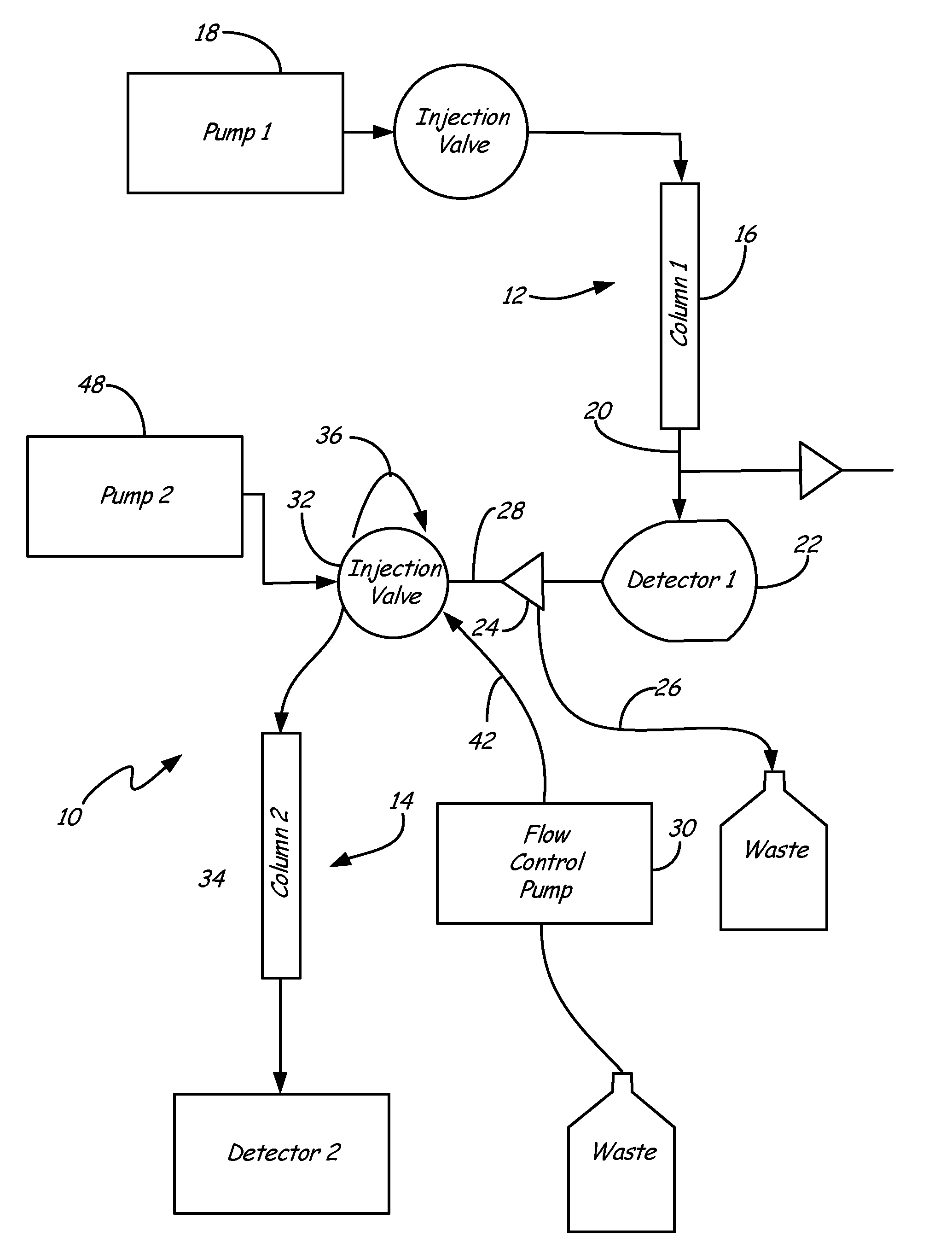
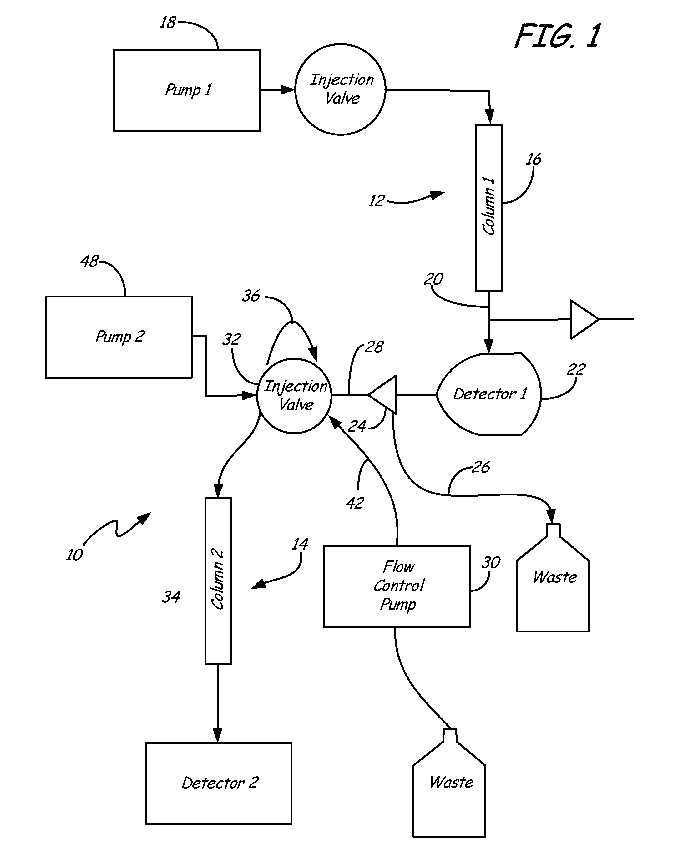
[0031]To effectuate consistent splitting of effluent flow from a first dimension analysis column in a manner to preserve the first dimension separation resolution, a positive displacement pump, such as a syringe pump, may be employed in a negative displacement mode to intake fluid at a specific rate from one outlet of a flow splitter. The resultant flow from a second outlet of the flow splitter is also therefore controlled. Such control dictates that the flow rate in both outlets of the split is known.

[0032]A first schematic diagram of an arrangement of the present invention is provided in FIG. 1. Analysis system 10 includes a first dimension separation system 12, and a second dimension separation system 14, wherein mobile phase is driven through a first dimension separation column 16 by a first dimension pump 18. First dimension outflow 20 from column 16 may be delivered to a first dimension chromatographic detector 22, or may first be split by a flow splitter. Flow rate into flow ...


PUM

PropertyMeasurementUnit
pressureaaaaaaaaaa
pressureaaaaaaaaaa
multi-dimensional liquid analysisaaaaaaaaaa

Abstract

A multi-dimensional liquid analysis system includes a flow splitter for separating mobile phase outflow from a first dimension liquid analysis system into first and second liquid split outlet flows. Volumetric flow rate control of the split outlet flows is provided by a flow control pump which withdraws one of the split outlet flows from the flow splitter at a controlled withdrawal flow rate to define the other split outlet flow rate as the difference between the outflow rate from the first dimension system and the withdrawal flow rate. In this manner, accurate and consistent flow division can be accomplished, which is particularly useful for multi-dimensional liquid analysis.

Description

CROSS-REFERENCE TO RELATED APPLICATIONS[0001]This application claims priority to U.S. Provisional Patent Application Ser. No. 61 / 466,739, filed on Mar. 23, 2011 and entitled “Valve and Splitting System for Two-Dimensional Liquid Chromatography,” the content of which being incorporated herein in its entirety.FIELD OF THE INVENTION[0002]The present invention relates to flow systems used in analytical chemistry, and more particularly to a splitting system for splitting mobile phase flow in a multi-dimensional liquid chromatography apparatus.BACKGROUND OF THE INVENTION[0003]Separation techniques such as high pressure liquid chromatography (HPLC) are commonly used in analytical chemistry. However, HPLC is limited by the resolution which can be achieved using a single chromatographic separation column. Attempts have been made to combine two or more liquid chromatographs into a hybrid instrument to achieve enhanced resolution of more compounds than can be achieved in a single separation co...

Claims


Application Information

Patent Timeline
Patent Type & Authority Applications(United States)
IPC IPC(8): G01N30/02
CPCG01N30/463G01N30/465G01N30/7233G01N2030/324G01N30/10G01N30/32
Inventor SIMS, CARL
Owner RGT UNIV OF MINNESOTA
Why Eureka
Try Eureka