
Support stand

Active Publication Date: 2012-09-27
PEGATRON
View PDF9 Cites 9 Cited by
  • Summary
  • Abstract
  • Description
  • Claims
  • Application Information

AI Technical Summary

Benefits of technology

[0007]The disclosure is to provide a support stand that occupies less space as in storage and has better integrity.
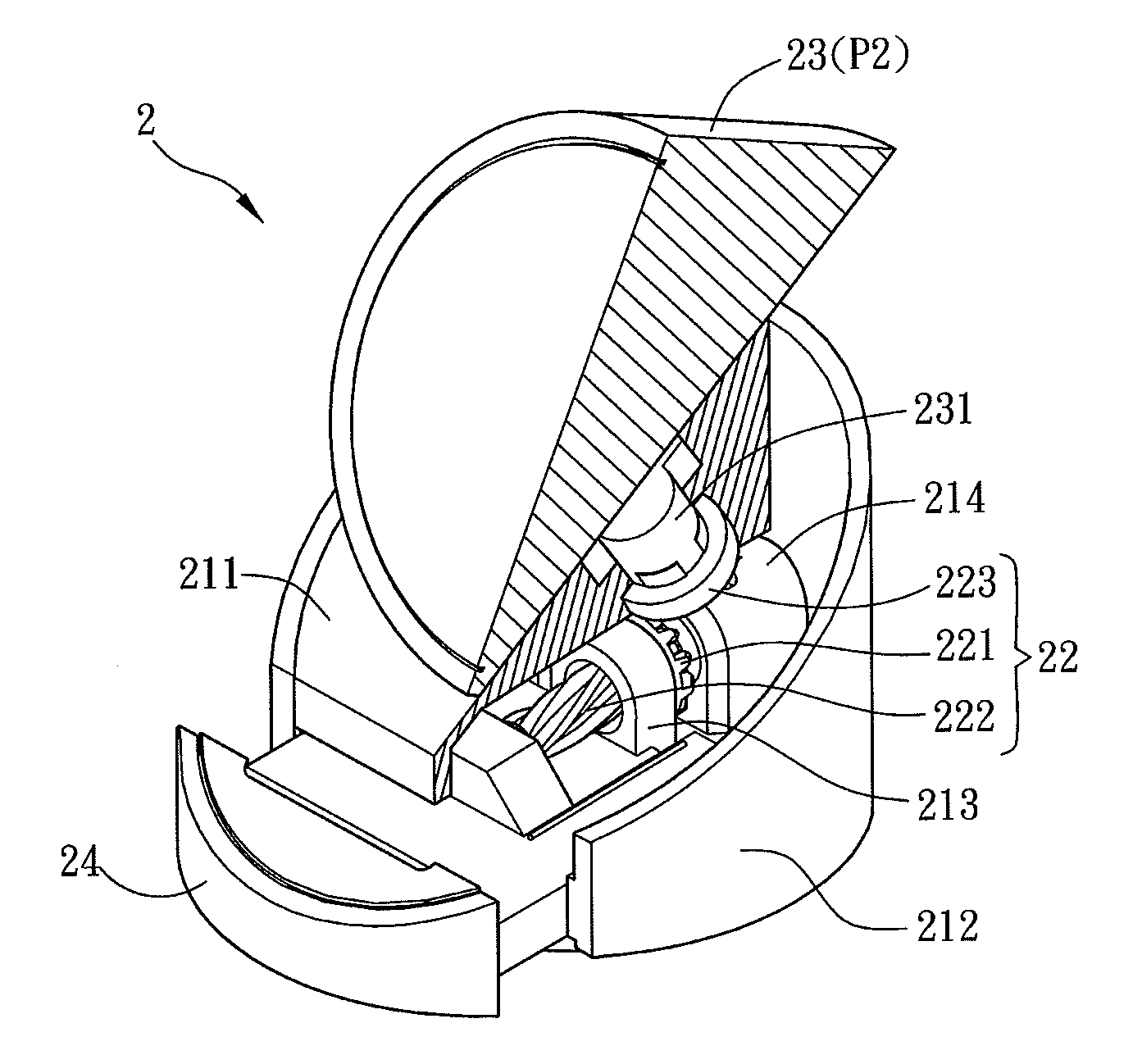
[0017]As mentioned above, in the support stand of the embodiment, the holder is received in the first casing as the second casing is located at the first position relative to the first casing. In addition, when the second casing is rotated to the second position relative the first casing, the second casing drives the first gear of the rotary mechanism to coordinately rotate the threaded rod so as to push the holder out of the first casing. The holder is received in the first casing as the support stand of the present invention is at the first position (storage position), so that the support stand occupies less space. Otherwise, when the second casing is rotated to the second position (supporting position), the second casing can drive the rotary mechanism to rotate so as to push the holder out of the first casing for supporting an object. Accordingly, the support stand of the present invention is suitable for supporting an object. Besides, when it is not in use, the holder can be stored in the first casing, so that the support stand can occupy less space and has better integrity. Moreover, the support stand of the present can be easily operated.

Problems solved by technology

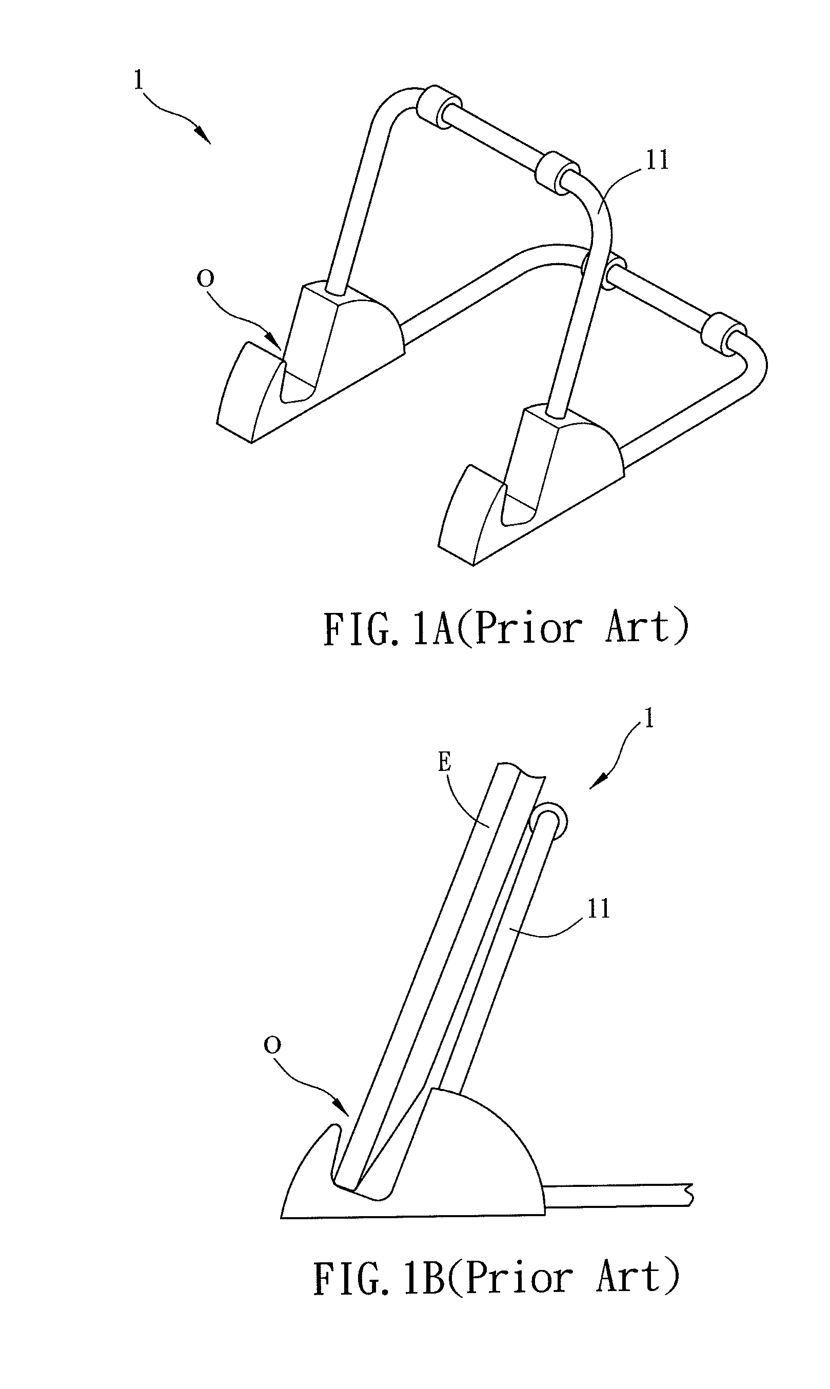
Unfortunately, while the conventional support stand 1 is not in use, it must be disassembled for storage and can not be properly stored as a whole.
In other words, the support stand 1 does not provide a proper storage, and it does not have a good integrity.

Method used


Image

  • Support stand
  • Support stand
  • Support stand

Examples


Embodiment Construction

[0029]The present invention will be apparent from the following detailed description, which proceeds with reference to the accompanying drawings, wherein the same references relate to the same elements.

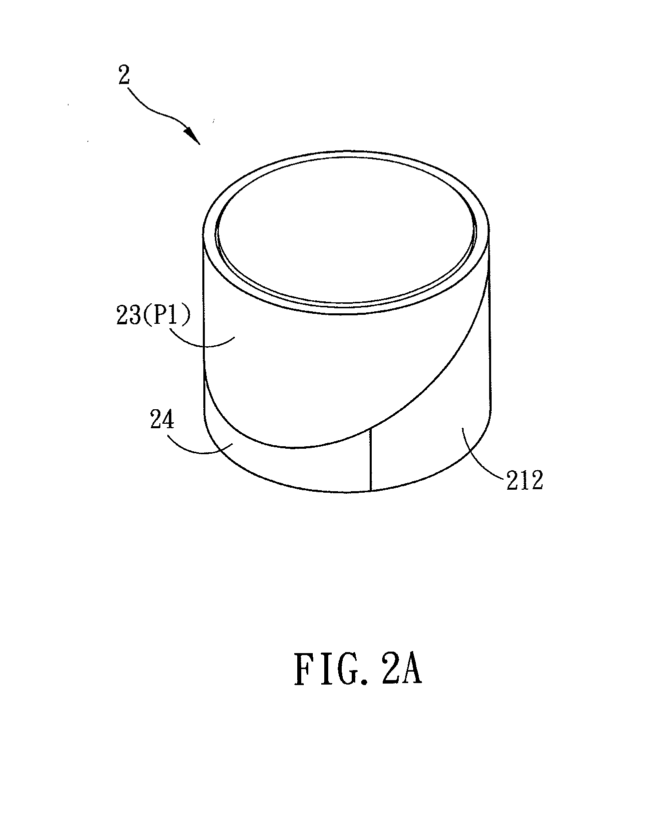
[0030]FIG. 2A is a schematic diagram showing a support stand 2, which is in a storage position, according to an embodiment of the present invention, and FIG. 2B is an exploded view of the support stand 2. Referring to FIG. 2A, the support stand 2 is not in use and it is in a storage position. Obviously, the support stand 2 has good integrity and occupies less space. Alternatively, the shape of the support stand 2 may be a polyhedron, such as a cylinder, a cube, or other shapes. In this case, the shape of the support stand 2 is a cylinder. Furthermore, the support stand 2 can be applied to support, for example, a paper document or an electronic device such as a tablet computer, a touch-screen cell phone, an e-paper, or a GPS.

[0031]The support stand 2 includes a first casing 21, a rotar...


PUM


Abstract

A support stand includes a first casing, a rotary mechanism, a second casing and a holder. The rotary mechanism is disposed in the first casing and has a first gear and a threaded rod coordinated with each other. The second casing is connected with the rotary mechanism. The second casing is able to rotate from a first position to a second position in relative to the first casing. The holder is connected with the threaded rod. When the second casing is at the first position, the holder is stored in the first casing. When the second casing is rotated to the second position, the second casing drives the first gear to coordinately rotate the threaded rod so as to push the holder out of the first casing. The support stand occupies less space as the holder is stored, and it has better overall integrity.

Description

CROSS REFERENCE TO RELATED APPLICATIONS[0001]This Non-provisional application claims priority under 35 U.S.C. §119(a) on Patent Application No(s). 100109603 filed in Taiwan, Republic of China on Mar. 21, 2011, the entire contents of which are hereby incorporated by reference.BACKGROUND OF THE INVENTION[0002]1. Technology Field[0003]The disclosure relates to a support stand and, in particular, to a rotatable support stand.[0004]2. Related Art[0005]The conventional desktop support stands, such as the cell phone stands, e-paper stands, or tablet computer stands, are all have open designs. FIG. 1A is a perspective view of a conventional support stand 1 for a tablet computer, and FIG. 1B is a schematic diagram of the support stand 1 in use. As shown in FIGS. 1A and 1B, the support stand 1 has the same configuration in both the in-use mode and not-in-use mode. Accordingly, when the support stand 1 is not in use, it still occupies a certain space.[0006]In addition, since the support stand ...

Claims


Application Information

Patent Timeline
IPC IPC(8): F16M13/00
CPCA47B23/042F16M11/10H04M1/04F16M13/00F16M11/18
Inventor CHUNG, CHIH-CHENG
Owner PEGATRON
Learn More