Head-mounted display device and control method for the head-mounted display device

a display device and display device technology, applied in the direction of instruments, computing, electric digital data processing, etc., can solve the problems of affecting the operation, affecting the visibility of the user, and affecting the user's experience, so as to improve the visibility of an external scene

Active Publication Date: 2012-09-27
SEIKO EPSON CORP
View PDF8 Cites 211 Cited by
  • Summary
  • Abstract
  • Description
  • Claims
  • Application Information

AI Technical Summary

Benefits of technology

[0009]An advantage of some aspect of the invention is to provide, in a head-mounted display device, a technique for impro

Problems solved by technology

In the head mounted display explained above, when the user operates a control unit of the head mounted display for the purpose of, for example, playback, stop, and fast forward of a video, it is likely that a virtual image displayed before the eyes of the user blocks the visual field of the user and hinders the operation.
On the other hand, in a worn state of the head mounted display, since an image blocking an external scene is always displayed before the eyes of the user, the

Method used


Image

  • Head-mounted display device and control method for the head-mounted display device
  • Head-mounted display device and control method for the head-mounted display device
  • Head-mounted display device and control method for the head-mounted display device

Examples


first embodiment

A. First Embodiment

A-1. Configuration of a Head-Mounted Display Device

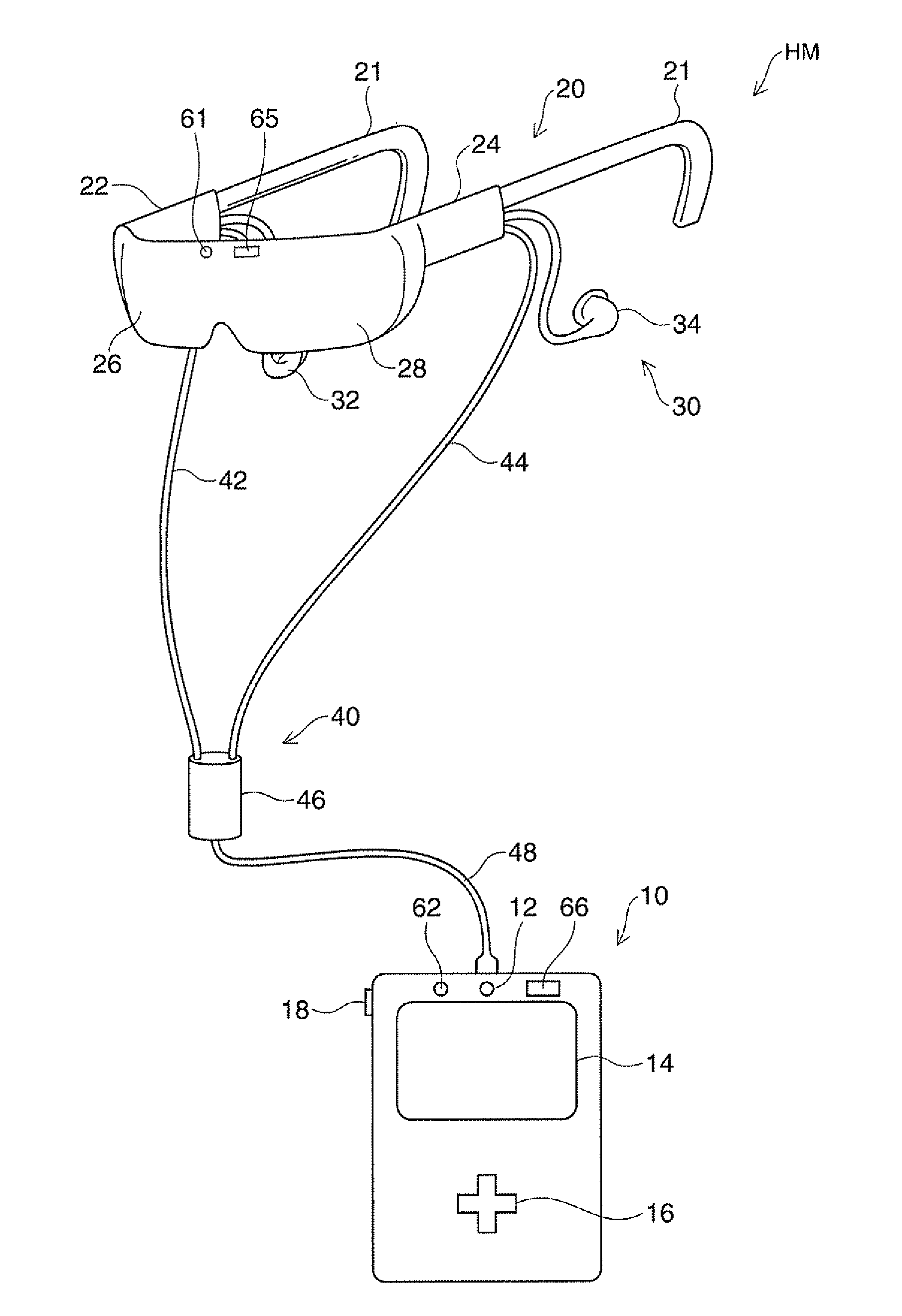
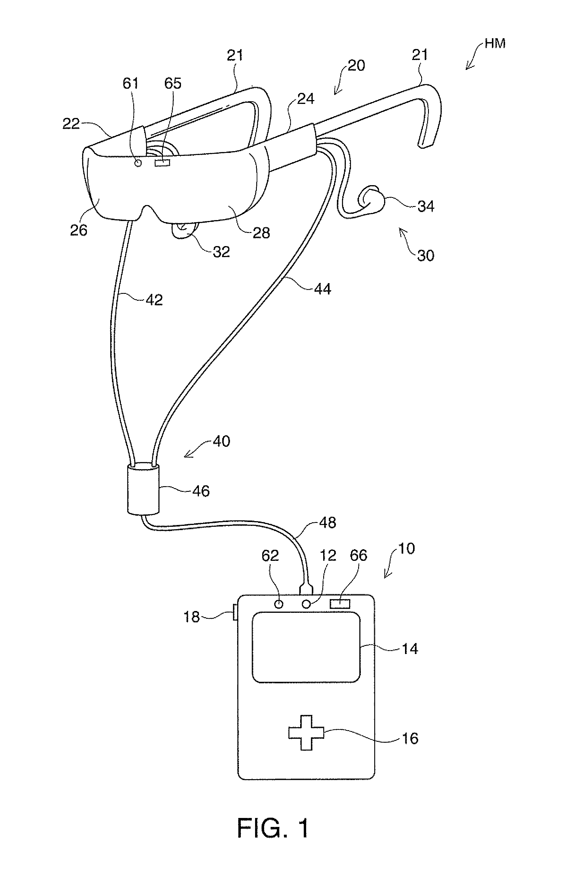
[0076]FIG. 1 is an explanatory diagram showing the configuration of the exterior of a head-mounted display in a first embodiment of the invention. A head-mounted display device HM is a display device mounted on the head and is also called head mounted display (HMD). The head mounted display NM in this embodiment is an optical see-through head-mounted display device with which a user can visually recognize a virtual image and at the same time directly visually recognize an external scene.

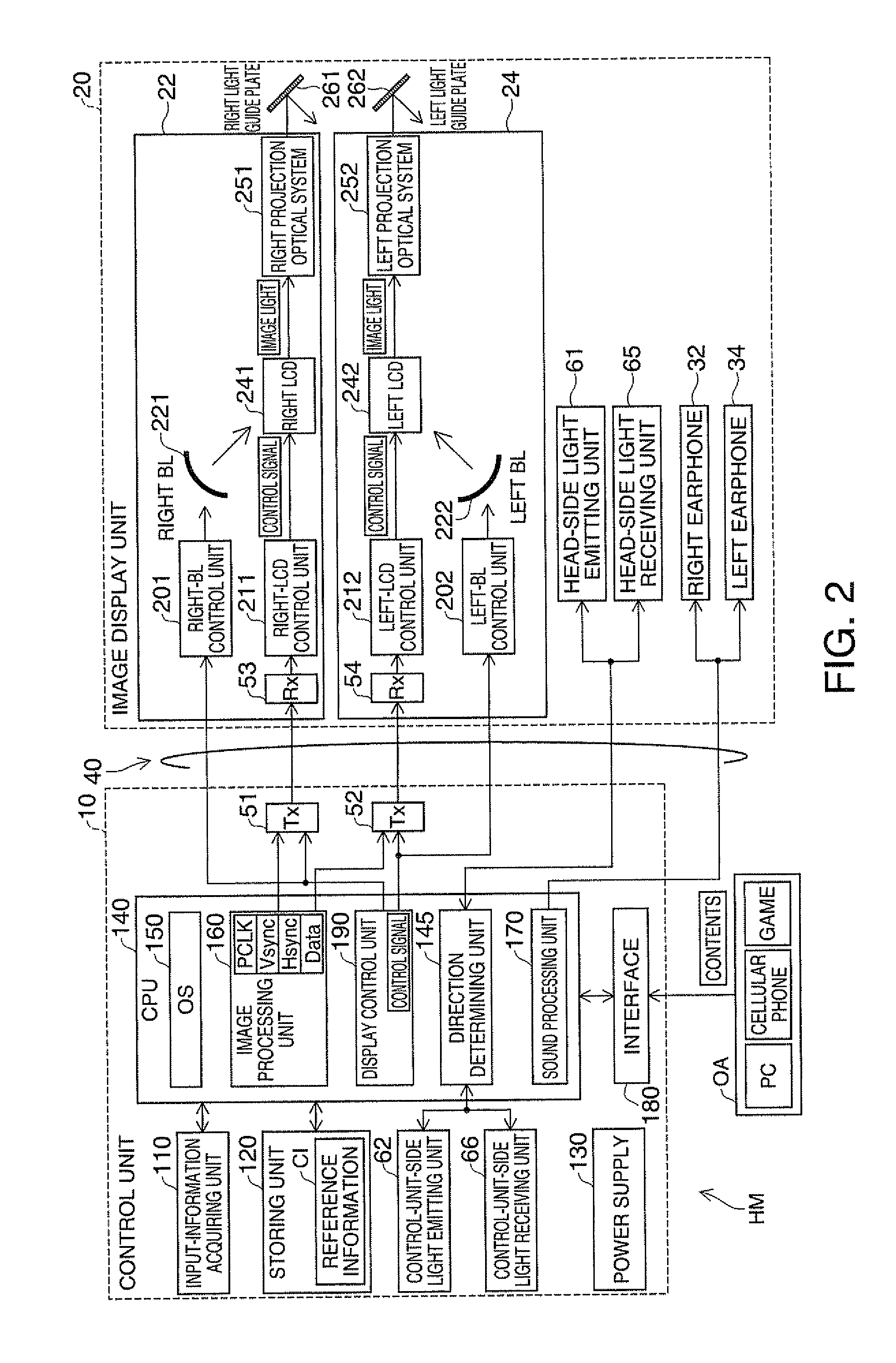
[0077]The head mounted display HM includes an image display unit 20 that causes the user to visually recognize a virtual image in a state in which the image display unit 20 is mounted on the head of the user and a control unit (a controller) 10 that controls the image display unit 20.

[0078]The image display unit 20 is a mounted member mounted on the head of the user. In this embodiment, the image display unit 20 has an eyeglass sha...

second embodiment

B. Second Embodiment

[0127]In a second embodiment of the invention, a configuration that can improve reliability and power saving properties in user-side see-through processing is explained. In the following explanation, only components having configurations and operations different from those in the first embodiment are explained. In the figures, components same as those in the first embodiment are denoted by reference numerals and signs same as those in the first embodiment explained above and detailed explanation of the components is omitted.

B-1. Configuration of a Head-Mounted Display Device

[0128]FIG. 9 is an explanatory diagram showing the configuration of the exterior of a head mounted display HMa in the second embodiment. FIG. 10 is a functional block diagram showing the configuration of the head mounted display HMa in the second embodiment. The head mounted display HMa is different from the head mounted display HM in the first embodiment shown in FIGS. 1 and 2 in that the hea...

third embodiment

C. Third Embodiment

[0135]In a third embodiment of the invention, a configuration for performing, instead of the user-side see-through processing, movement detection processing for detecting the movement of the head exceeding a fixed amount of a user wearing an image display unit is explained. In the following explanation, only components having configurations and operations different from those in the first embodiment are explained. In the figures, components same as those in the first embodiment are denoted by reference numerals and signs same as those in the first embodiment explained above and detailed explanation of the components is omitted.

C-1. Configuration of a Head-Mounted Display Device

[0136]FIG. 12 is an explanatory diagram showing the configuration of the exterior of a head-mounted display device according to the third embodiment. FIG. 13 is a functional block diagram of the configuration of a head mounted display HMb in the third embodiment. The head mounted display HMb...


PUM


Abstract

A head-mounted display device includes: an image display unit including an image-light generating unit that generates image light representing an image and emits the image light and a light guide unit that guides the emitted image light to the eye of a user, the image display unit being for causing the user to visually recognize a virtual image; and a control unit that includes an operation surface, is connected to the image display unit, and controls image display by the image display unit. When it is assumed that the user shifts the user's attention from the virtual image, the control unit adjusts the luminance of the image-light generating unit or adjusts the image light generated by the image-light generating unit to reduce the visibility of the virtual image.

Description

BACKGROUND[0001]1. Technical Field[0002]The present invention relates to a head-mounted display device, which is a display device mounted on the head, and a control method for the head-mounted display device.[0003]2. Related Art[0004]There is known a head-mounted display device (a head mounted display, HMD), which is a display device mounted on the head. For example, the head-mounted display device generates image light representing an image using a liquid crystal display and a light source and guides the generated image light to the eyes of a user using a projection optical system and a light guide plate to thereby cause the user to recognize a virtual image.[0005]In the head mounted display explained above, when the user operates a control unit of the head mounted display for the purpose of, for example, playback, stop, and fast forward of a video, it is likely that a virtual image displayed before the eyes of the user blocks the visual field of the user and hinders the operation....

Claims


Application Information

Patent Timeline
IPC IPC(8): G09G5/00
CPCG09G3/3406G02B2027/0187G02B2027/0118G02B27/017G02B27/0093G02B27/0172G02B2027/0138G02B2027/014G02B2027/0178G06F3/041
Inventor NAKADA, YUJISAITO, HITOSHI
Owner SEIKO EPSON CORP
Why Eureka
Try Eureka