
Video surveillance apparatus using dual camera and method thereof

Inactive Publication Date: 2012-09-27
UDP TECH
View PDF6 Cites 39 Cited by
  • Summary
  • Abstract
  • Description
  • Claims
  • Application Information

AI Technical Summary

Benefits of technology

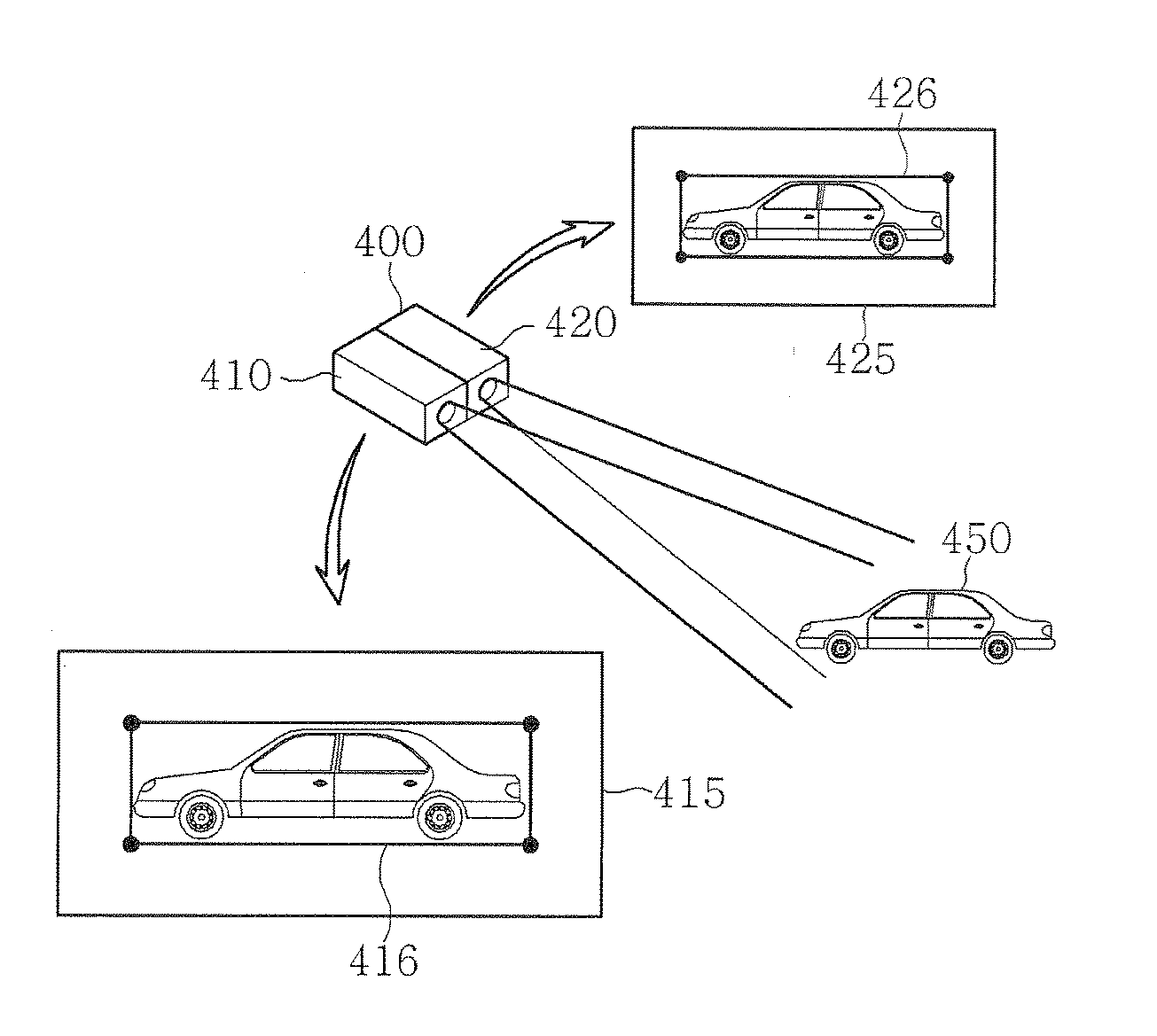
[0018]Accordingly, it is an object of the present invention to provide a video surveillance apparatus and method using a dual camera unit including a visible light camera and a special-purpose camera such as a thermal image or an infrared camera, which is capable of performing video analysis through a video of one camera having a higher surveillance effect and displaying a result of the analysis on a video of another camera, so that continuity of surveillance and result display can be maintained even if an operator selects any camera video as an output video.
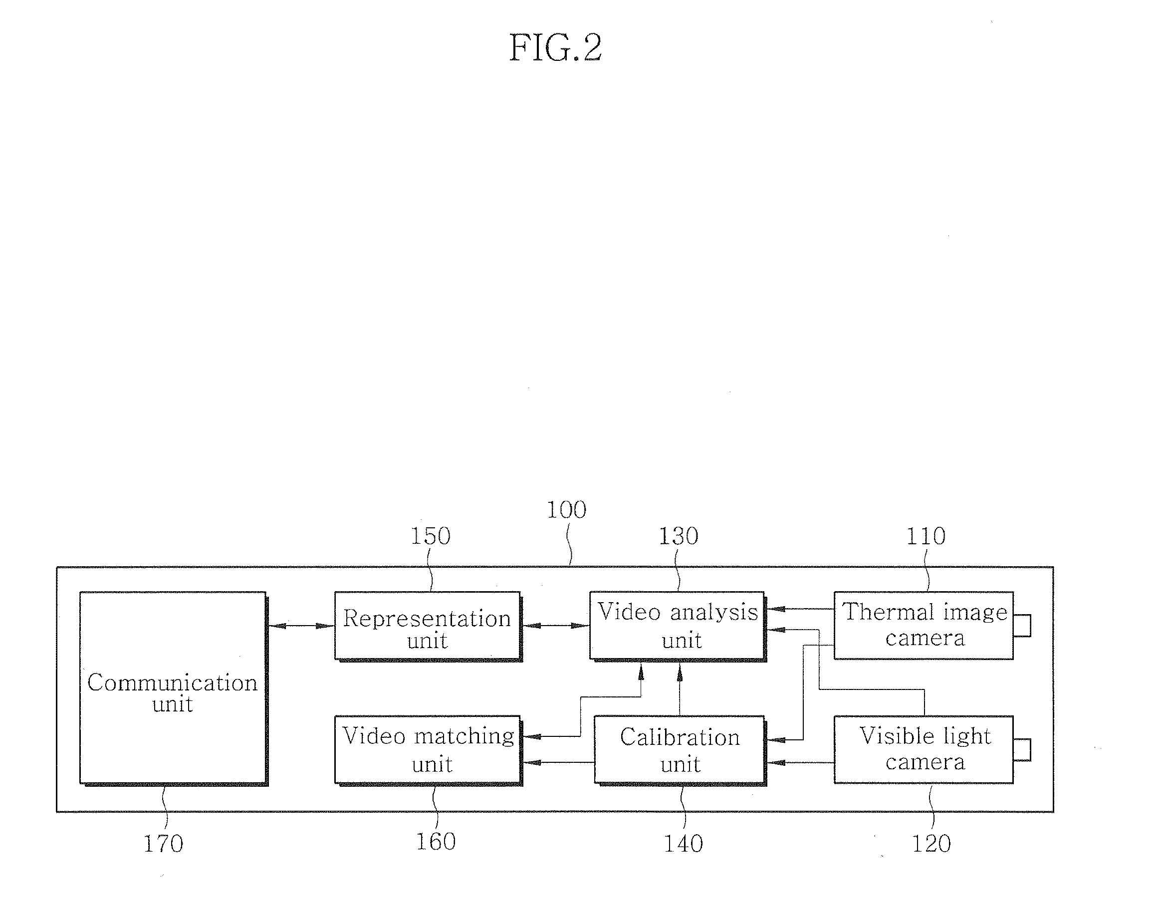
[0030]According to an embodiment of the present invention, since the video surveillance apparatus and method using the dual camera unit is capable of acquiring matching information using at least one of a parameter obtained through calibration between cameras, a two-dimensional image obtained through each camera, and a three-dimensional space oriented by each camera, analyzing a video of one selected from the cameras, performing object tracking based on a result of the analysis, and matching and displaying a position of a bounding box corresponding to a result of the object tracking to a video of the other camera, even when video analysis is performed for a video of one camera having a higher surveillance effect, a result of the analysis can be displayed on a video of another camera, which may result in efficient video surveillance depending on a selection by an operator.
[0031]According to an embodiment of the present invention, since the video surveillance apparatus and method using the dual camera unit including a visible light camera and a special-purpose camera such as a thermal image or an infrared camera is capable of performing video analysis through a video of the thermal image or the infrared camera and reflecting a result of the analysis in a megapixel video through matching, it is possible to achieve real time video analysis for the entire surveillance area while performing E-PTZ for a desired surveillance area, application of a result of the analysis to an E-PTZ screen displaying a partial area, and reflection of the real time video analysis result even in the event of changes in a video, such as E-PTZ scene switching, position movement, zooming and so on.
[0032]According to an embodiment of the present invention, since the video surveillance apparatus and method using the dual camera unit including a visible light camera and a special-purpose camera such as a thermal image or an infrared camera is capable of arranging a visible light camera and a special-purpose camera in the same surveillance area, securing FOV differences between these cameras as pixel matching parameters between images by the medium of the same space corresponding to an image of each camera, performing selective video analysis for one of these parameters, and checking a result of the analysis in any camera images through the matching information in the same way, it is possible to guarantee autonomy of video switching, continuity of object tracking in video switching, and high reliability.

Problems solved by technology

However, when the general visible light camera is used, in some cases, due to insufficient amount of light, reflection or movement of light, inflow of direct light ray, or other noises, a false alarm may occur or objects may not be detected, or object tracking is broken off to lower reliability for tracking.
In particular, in case of a wide surveillance area, it is often difficult to secure a proper level of illuminance for the entire surveillance area and quality of video analysis sources may be deteriorated due to motion of unspecified light or noises such as yellow sands, dusts and so on.
Accordingly, since effective video surveillance should be achieved with only limited computational resources of a video analysis device implemented in each camera, it is difficult to add a complicated configuration for mitigation of the above-mentioned visible camera limitation or perform an excessive computation.
In order to achieve effective surveillance for the megapixel video, analysis for the entire video has to be performed simultaneously with analysis for a partial video to be actually surveiled and transmitted, which results in increase in a load of the video analysis unit incorporated in the camera and hence increase in camera costs.
Even in this case, there is still a problem of low reliability due to insufficient amount of light, reflection or movement of light, inflow of direct light ray, or other visible noises, which are limits as to the visible light camera, as mentioned previously.
However, both of these units still have limits due to ambient environments and noise since they use only the visible light cameras.
However, since video analysis in such switching has to be again carried out in compliance with a video of each camera, continuity of surveillance disappears.
However, in case where an event occurs, only a video of the infrared camera is used to check abnormality, which may lead to a risk of misjudgement.
In addition, when the video of the infrared camera is switched to the video of the visible light camera, there arises a problem of missing of existing video analysis results.

Method used


Image

  • Video surveillance apparatus using dual camera and method thereof
  • Video surveillance apparatus using dual camera and method thereof
  • Video surveillance apparatus using dual camera and method thereof

Examples


Embodiment Construction

[0043]Hereinafter, embodiments of the present invention will be described in detail with reference to the accompanying drawings.

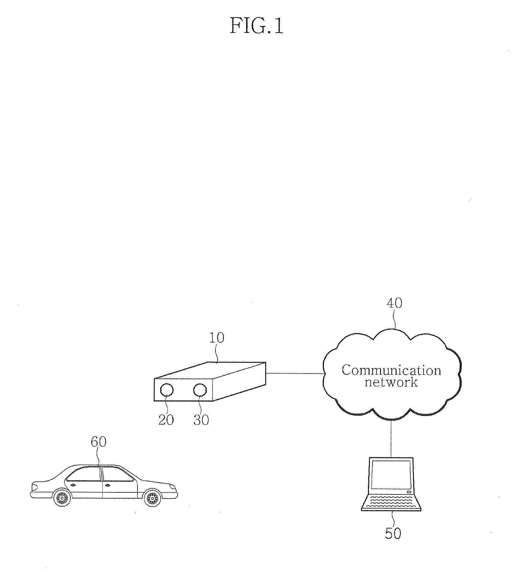
[0044]FIG. 1 shows an exemplary surveillance system to which a video surveillance apparatus using a dual camera according to an embodiment of the present invention is applied. Referring to FIG. 1, the surveillance system includes a video surveillance apparatus 10 including a dual camera unit composed of different kinds of cameras 20 and 30 which are placed adjacent to each other and configured to surveil (or monitor) an object 60 (for example, a car) in the same surveillance area; and a control center 50 which is connected to the video surveillance apparatus 10 via a communication network 40, provides control information on the dual camera unit, and checks a video provided by the video surveillance apparatus 10.

[0045]The different kinds of cameras 20 and 30 of the dual camera unit are preferably a visible light camera and a special-purpose camera, such as a...


PUM


Abstract

The present invention relates to a video surveillance apparatus and method using a dual camera, which is capable of applying any camera videos with a result of video analysis made based on one selected from videos provided from a special purpose camera, such as a thermal image camera, and a visible light camera. Since the video surveillance apparatus and method is capable of arranging a visible light camera and a special-purpose camera in the same surveillance area, securing FOV differences between these cameras as pixel matching parameters between images by the medium of the same space corresponding to an image of each camera, performing selective video analysis for one of these parameters, and checking a result of the analysis in any camera images through the matching information in the same way, it is possible to guarantee autonomy of video switching, continuity of object tracking in video switching, and high reliability.

Description

CROSS-REFERENCE TO RELATED APPLICATION[0001]This application claims the benefit of Korean Application No. 10-2011-0025124, filed on Mar. 22, 2011, with the Korean Intellectual Property Office, the disclosure of which is incorporated herein by reference.BACKGROUND OF THE INVENTION[0002]1. Field of the Invention[0003]The present invention relates to a video surveillance apparatus and method using a dual camera, and more particularly, a video surveillance apparatus and method using a dual camera, which is capable of applying any camera videos with a result of video analysis made based on one selected from videos provided from a special purpose camera, such as a thermal image camera, and a visible light camera.[0004]2. Description of the Related Art[0005]With advance of various imaging equipments, intelligent video surveillance technologies have been developed for surveiling events based on object motion within a video obtained by relevant imaging equipment according to a predetermined ...

Claims


Application Information

Patent Timeline
IPC IPC(8): H04N7/18H04N13/04
CPCG08G1/0175H04N5/332G08B13/19643H04N23/11
Inventor WHITE, BENROBINSON, NEILCHOO, YEON HAK
Owner UDP TECH
Learn More