

Oscillating weight for automatic watch
Active Publication Date: 2012-09-27
CHRISTIAN DIOR COUTURE
View PDF9 Cites 21 Cited by
- Summary
- Abstract
- Description
- Claims
- Application Information
AI Technical Summary
Benefits of technology
[0011]Another object of the invention consists in providing an oscillating weight that allows the other elements of the movement to be at least partly visible.
[0022]Also advantageously, the weight is adapted to be positioned in front of the dial of the watch that it is intended to wind up. This position enables the wearer to best enjoy the aesthetic qualities of the oscillating weight whilst enjoying a visual means to remember the necessity of performing at the appropriate time the motions required to wind up the watch movement.
Problems solved by technology
The oscillating weight however lacks visual or decorative elements.
This type of arm does not allow aesthetic or decorative elements to be machined in a reliable and durable manner.
This type of arm also does not allow aesthetic or decorative elements to be machined in a reliable and durable manner.
This type of configuration strongly restricts the zones likely to bear diamonds, thus reducing their visibility accordingly.
The designers also have no possibilities for creating original visual arrangements other than in the shape of an arc of circle along the ring.
Method used
View moreImage
Smart ImageViewing Examples

Examples
first embodiment
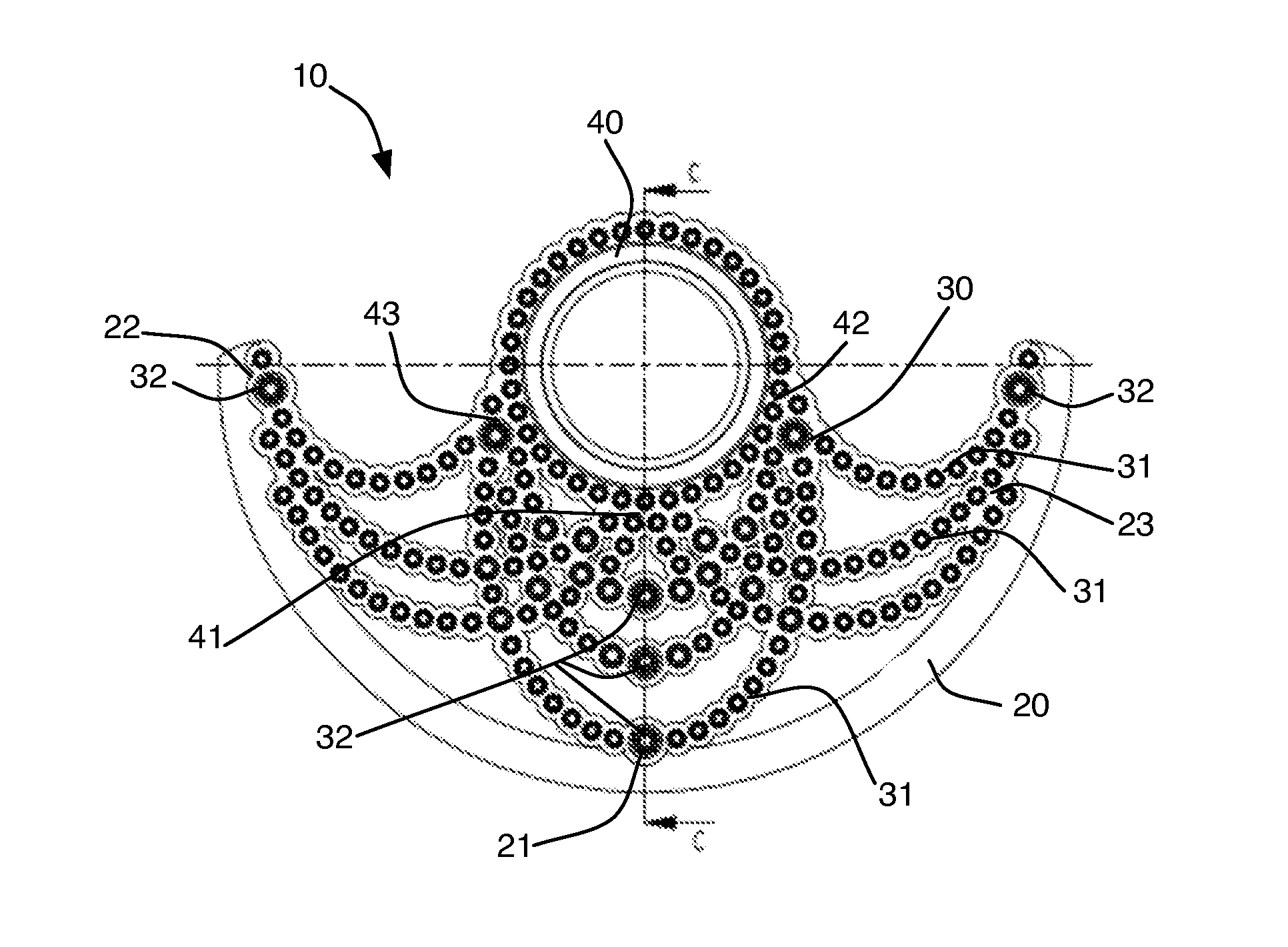
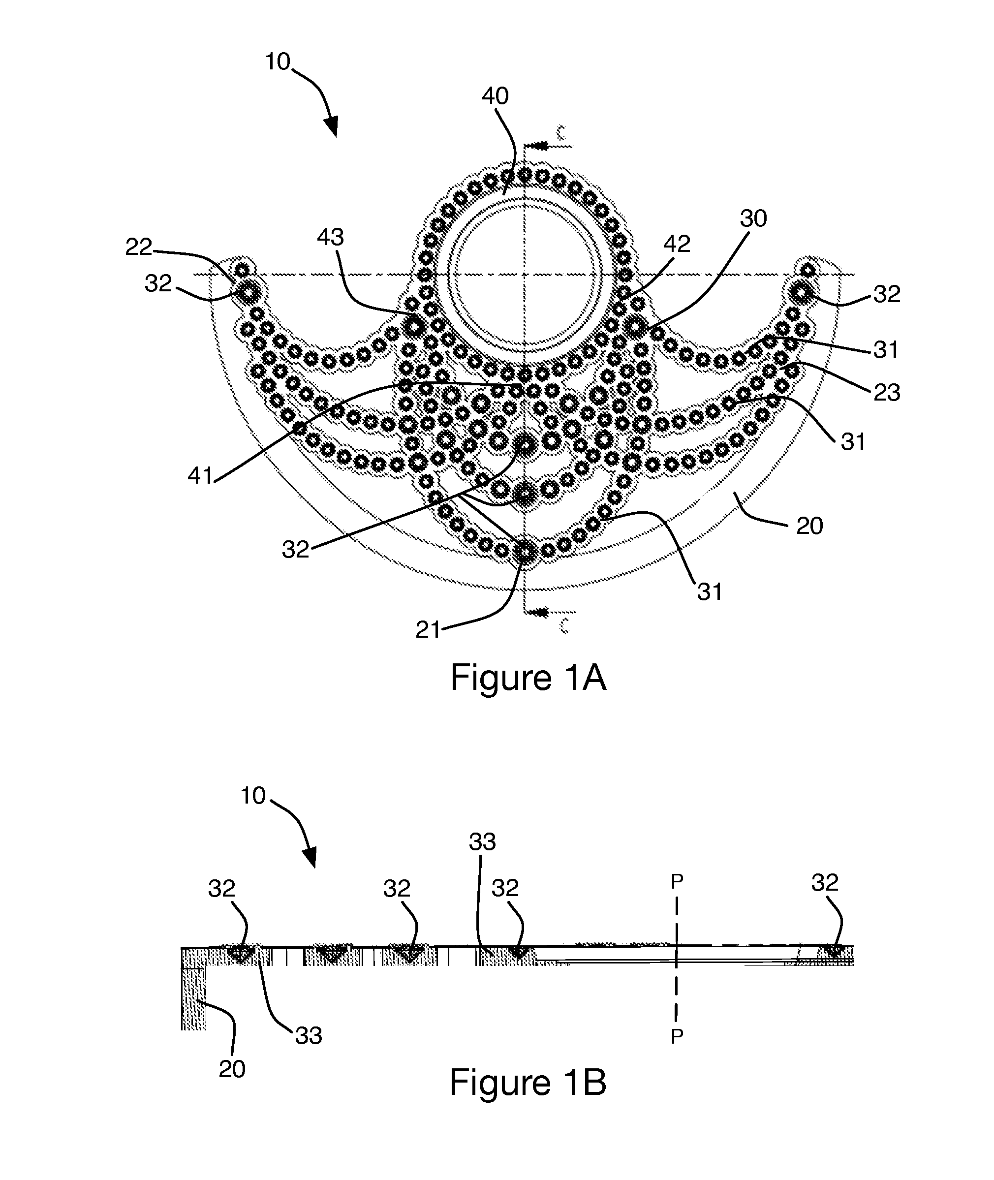
[0032]FIG. 1A is a top view of an oscillating weight according to the invention;
[0033]FIG. 1B is a cross-section view, along the arrow C-C, of the oscillating weight shown in FIG. 1A;
second embodiment
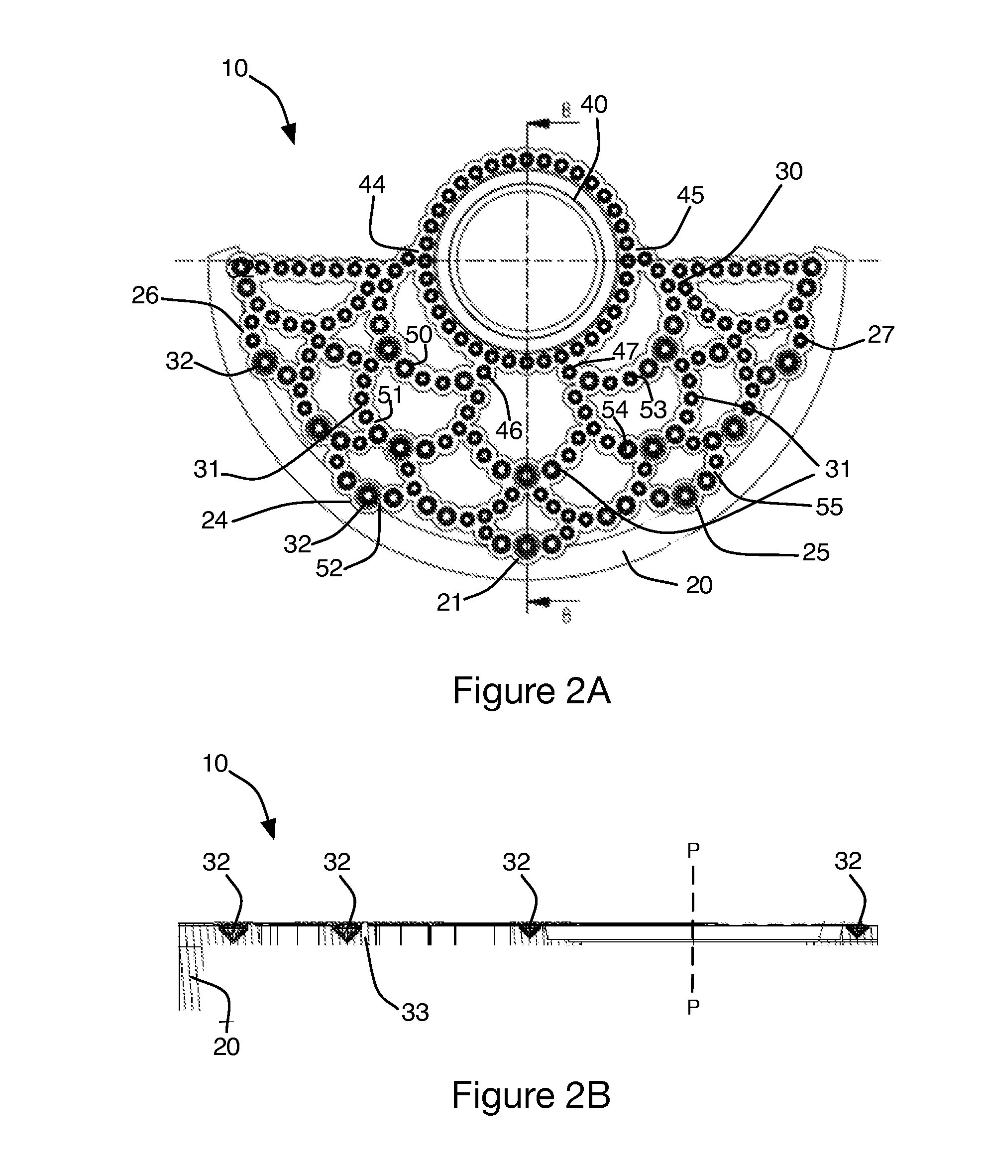
[0034]FIG. 2A is a top view of an oscillating weight according to the invention;
[0035]FIG. 2B is a cross-section view, along the arrow B-B, of the oscillating weight shown in FIG. 2A;
third embodiment
[0036]FIG. 3A is a top view of an oscillating weight according to the invention;
[0037]FIG. 3B is a cross-section view, along the arrow A-A, of the oscillating weight shown in FIG. 3A.
Login to View More PUM
 Abstract
Oscillating weight for automatic watch movement, having a massive peripheral ring in the shape of an arc of circle, a connecting element connecting the peripheral ring to the weight's pivoting center, wherein the connecting element is set with a plurality of stones.
Description
[0001]The present application claims priority from Swiss patent application CH522 / 11, filed on Mar. 23, 2011, the content of which being hereby incorporated by reference.TECHNICAL FIELD OF THE INVENTION[0002]The present invention relates to oscillating weights for automatic watches.STATE OF THE PRIOR ART[0003]Oscillating weights for automatic watches are well known and widespread. An oscillating weight typically enables the winding-up function of a movement to be performed thanks to the weight's oscillations generated by the movements of the watch wearer. The weight is mounted in pivoting fashion, for example by means of a bearing, and with a reverser ensuring that the weight's alternating movement is transformed into a unidirectional rotating movement. The reduction geartrains of the winding mechanism ensure the connection between the different elements. Driving the winding mechanism in rotation makes it possible to wind up the barrel spring.[0004]In classical fashion, the oscillat...
Claims
Login to View More Application Information
Patent Timeline
 IPC IPC(8): G04B5/16G04B5/02
CPCG04B5/16
InventorJAMIN, MATHIEUFERRAND, MATHIEULEBRETON, ETIENNE
OwnerCHRISTIAN DIOR COUTURE