Wearable battery set

a battery set and wearable technology, applied in the direction of flat cell grouping, primary cell maintenance/service, sustainable manufacturing/processing, etc., can solve the problems of battery running out of power more frequently, affecting the user's use of portable electronic devices, and greatly restricting the power capacity they can provid

Inactive Publication Date: 2012-09-27
TEX RAY IND
View PDF4 Cites 38 Cited by
  • Summary
  • Abstract
  • Description
  • Claims
  • Application Information

AI Technical Summary

Benefits of technology

[0009]To solve the aforesaid problem, a wearable battery set is provided in the present invention. The wearable battery set comprises a buckle and a flexible battery unit. The buckle comprises a control circuit. The flexible battery unit is disposed on a side of the buckle and connected to the control circuit electrically. The flexible battery unit is adapted to be bent ...

Problems solved by technology

Unfortunately, as batteries are decreased in volume, the power capacity they can provide will be greatly restricted.
Consequently, the battery will run out of power more frequently during the use of a portable electronic apparatus.
This not only makes it impossible for the user to continue to use the portable electronic apparatus, but...

Method used


Image

  • Wearable battery set
  • Wearable battery set
  • Wearable battery set

Examples


first embodiment

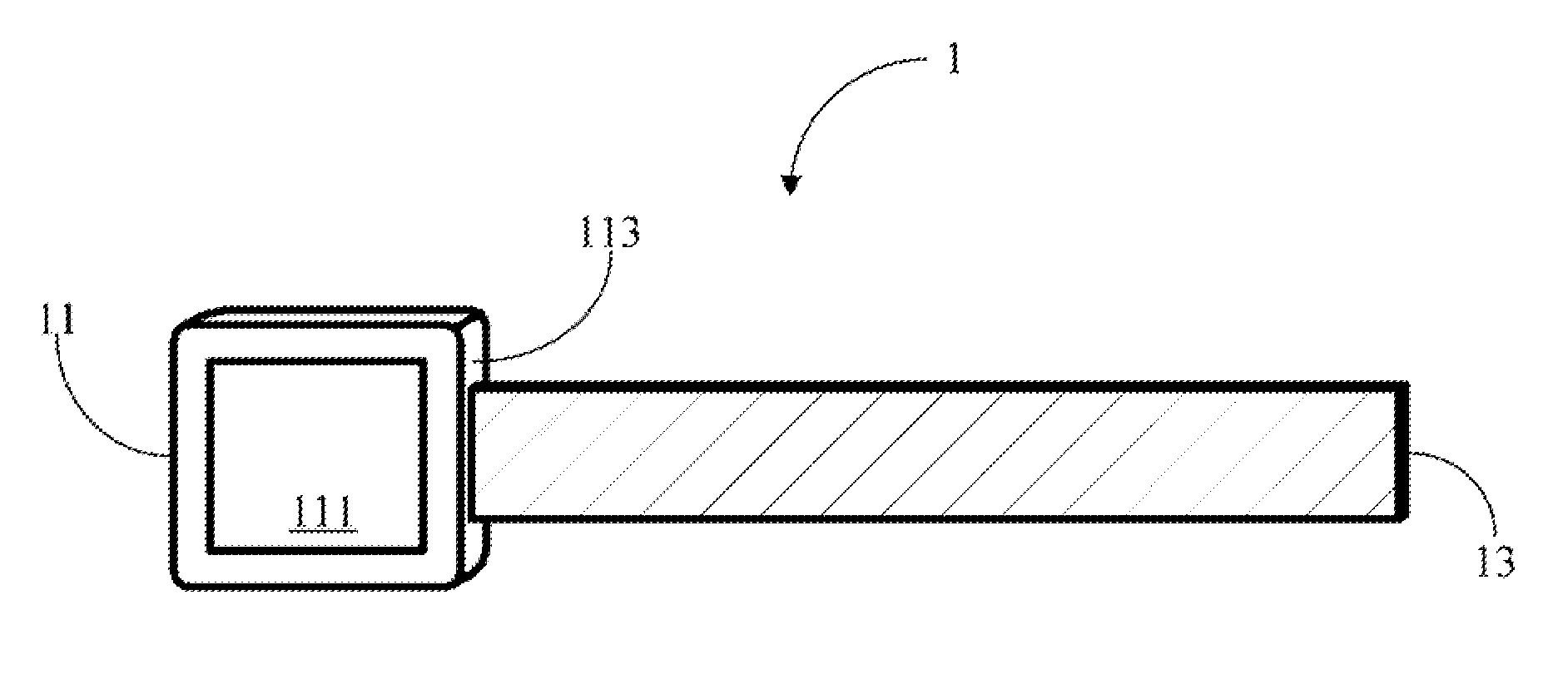
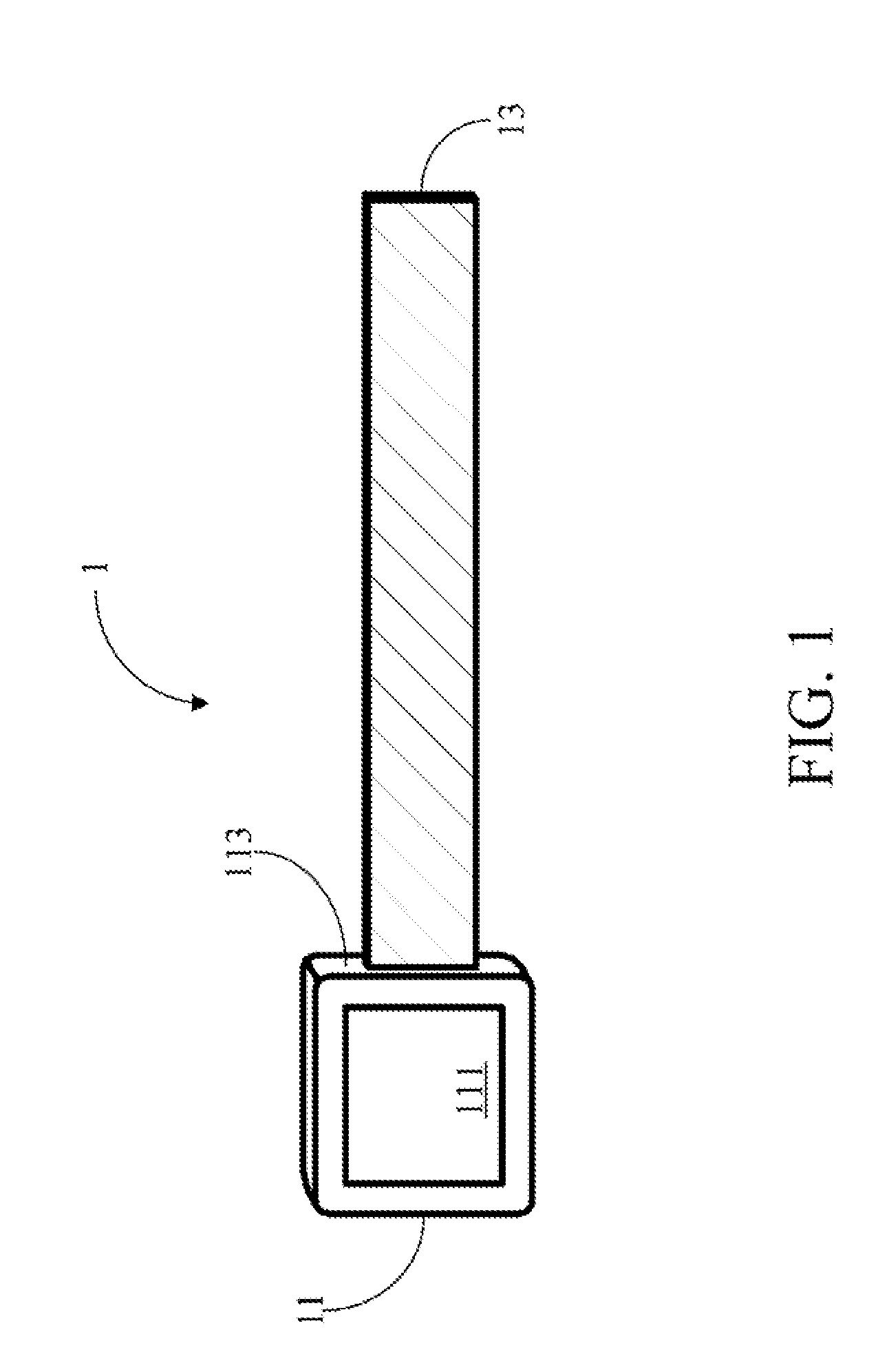
[0018]FIG. 1 illustrates a schematic view of a wearable battery set 1 according to the present invention. The wearable battery set 1 comprises a buckle 11 and a flexible battery unit 13. The buckle 11 comprises a control circuit 111. The flexible battery unit 13 is disposed on a side 113 of the buckle 11 and connected to the control circuit 111 within the buckle 11 electrically.

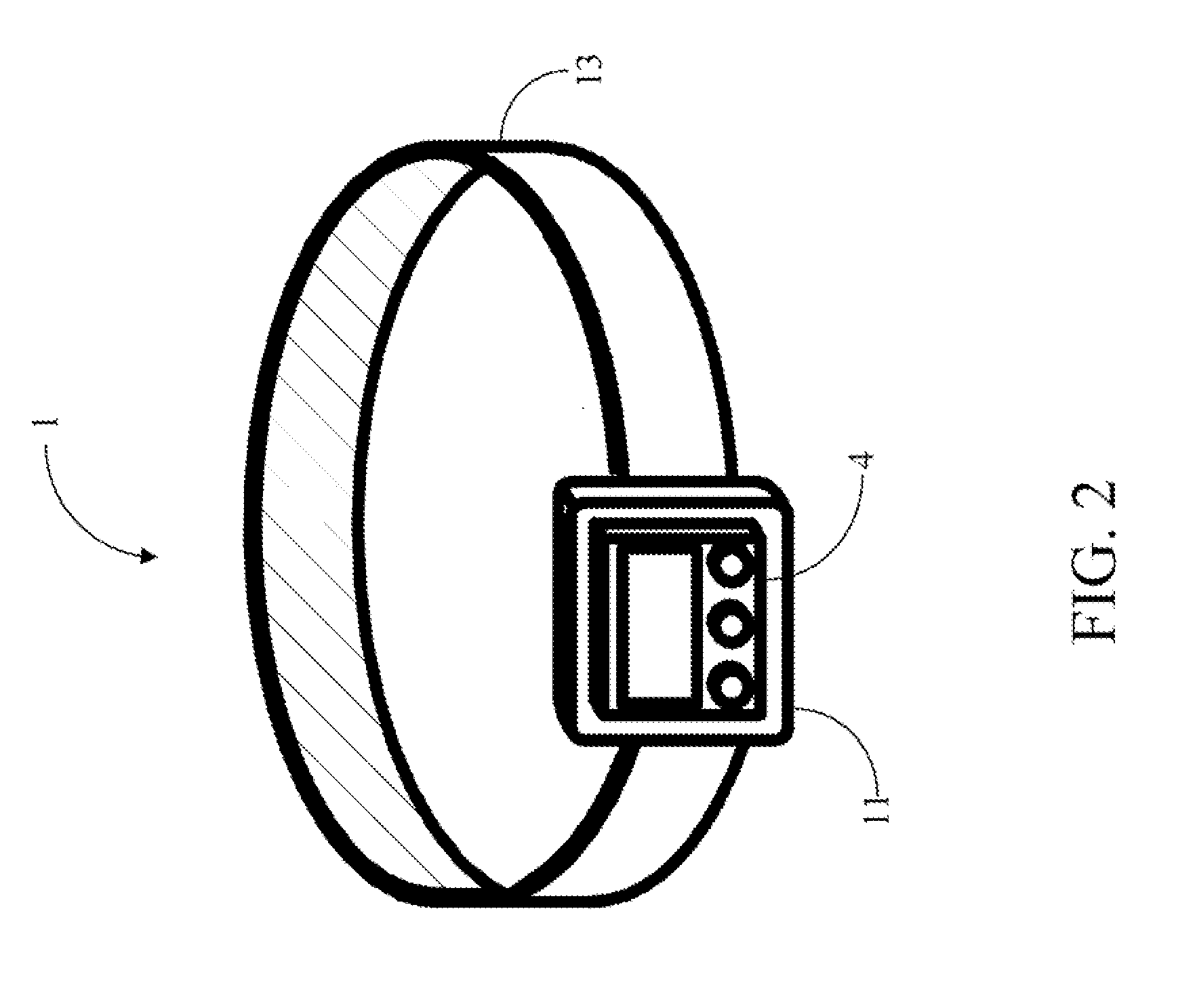
[0019]FIG. 2 illustrates a schematic view of the flexible battery unit 13 of the present invention in a bent status. As shown, the flexible battery unit 13 is adapted to be bent into a ring form, and the buckle 11 is adapted to keep the flexible battery unit 13 in the ring form so that the wearable battery set 1 can be worn by a user. It shall be particularly emphasized that in the first embodiment, the wearable battery set 1 is implemented as a belt so that it can be worn around the user's waist. However, this is not intended to limit the implementations of the wearable battery set 1; and in other embodiment...

third embodiment

[0024]FIG. 4 illustrates a schematic view of a wearable battery set 3 according to the present invention. The wearable battery set 3 comprises a buckle 31 and a flexible battery unit 33. The buckle 31 comprises a control circuit 311. The flexible battery unit 33 is disposed on a side 313 of the buckle 31 and is connected to the control circuit 311 electrically.

[0025]In the third embodiment, the flexible battery unit 33 may be provided with the flexibility through the interconnection of individual elements. Specifically, the flexible battery unit 33 comprises a plurality of battery sub-units 331 and a plurality of connecting elements 333. The connecting elements 333 are flexible circuit elements, which are disposed between the battery sub-units 331 respectively to connect the battery sub-units 331 physically and electrically.

[0026]FIG. 5 illustrates a schematic view of the flexible battery unit 33 of the present invention in a bent status. Likewise, as shown, the flexible battery uni...


PUM

PropertyMeasurementUnit
Poweraaaaaaaaaa
Flexibilityaaaaaaaaaa
Electric potential / voltageaaaaaaaaaa

Abstract

A wearable battery set is provided. The wearable battery set comprises a buckle and a flexible battery unit. The buckle has a control circuit. The flexible battery is disposed on the side of the buckle and connects to the control circuit electrically. The flexible battery unit is adapted to be bent into a ring, and the buckle is configured to keep the flexible battery unit in the ring form so that the wearable battery set can be worn by a user. The control circuit of the buckle is configured to control the output power of the flexible battery unit so that the wearable battery set is able to provide the output power to an electronic device via the control circuit of the buckle.

Description

[0001]This application claims priority to Taiwan Patent Application No. 100110261 filed on Mar. 25, 2011, which is hereby incorporated by reference in its entirety.CROSS-REFERENCES TO RELATED APPLICATIONS[0002]Not applicable.BACKGROUND OF THE INVENTION[0003]1. Field of the Invention[0004]The present invention relates to a wearable battery set. In particular, the wearable battery set of the present invention can be worn by a user and supply power to an electronic device.[0005]2. Descriptions of the Related Art[0006]With the continuous advancement of science and technology, various kinds of portable electronic apparatuses have been developed, and this brings great convenience to peoples' lives. Because good portability is of a great concern in the use of modern portable electronic apparatuses, they must be made to particularly have a small volume. In other words, in consideration of good portability, portable electronic apparatuses have become increasingly smaller; and correspondingly...

Claims


Application Information

Patent Timeline
IPC IPC(8): H01M10/00H01M50/209
CPCH01M2/1061H01M6/181H01M6/46H01M10/425H01M10/052H01M10/0565H01M10/4207H01M6/50Y02E60/10H01M50/209Y02P70/50
Inventor HUANG, HONG HSUPENG, JUNG HSIANG
Owner TEX RAY IND
Why Eureka
Try Eureka