Automated cascade impactor

a cascade impactor and automatic technology, applied in the field of automatic cascade impactors, can solve the problems of high cost, low throughput of conventional cascade impactors, and high operator-induced variabilities, and achieve the effect of reducing the number of operators and reducing the number of manual processes

Active Publication Date: 2012-10-04
LAB AUTOMATE TECH
View PDF0 Cites 9 Cited by
  • Summary
  • Abstract
  • Description
  • Claims
  • Application Information

AI Technical Summary

Benefits of technology

[0009]The foregoing and other objectives are achieved in accordance with the teachings and principles of the present invention through the provision of a new and improved automated cascade impactor which comprises a vertical array of a plurality of impactor stages, and a vertical array of isolation stages, wherein the vertical ar

Problems solved by technology

However, obtaining a dose determination from an Anderson cascade impactor is very labor intensive, error prone, time-consuming, and thus, a very expensive process.
For example, or more particularly, conventional procedures for obtaining particle size distribution data using conventional cascade impactors involves very low throughput results since conventional impactors require manual set-up procedures, operations, testing, and dose determination.
In addition, the manual process is very prone or susceptible to significant degrees of operator-induced variabilities impacting the generated data.
Each operator, that is, lab technician, analyst, or the like, washes or cleans the various components of the cascade impactor in different ways or modes thus causing incons

Method used


Image

  • Automated cascade impactor
  • Automated cascade impactor
  • Automated cascade impactor

Examples


Embodiment Construction

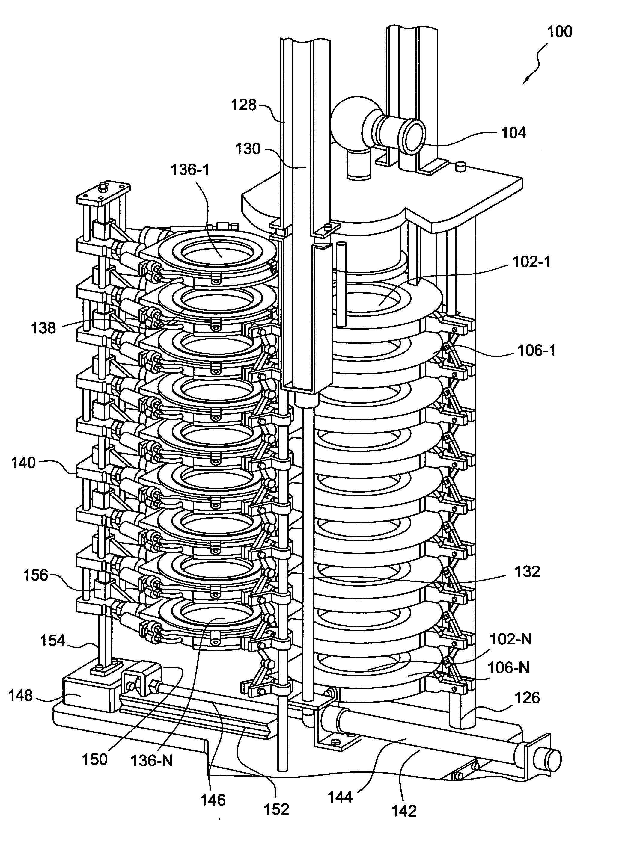
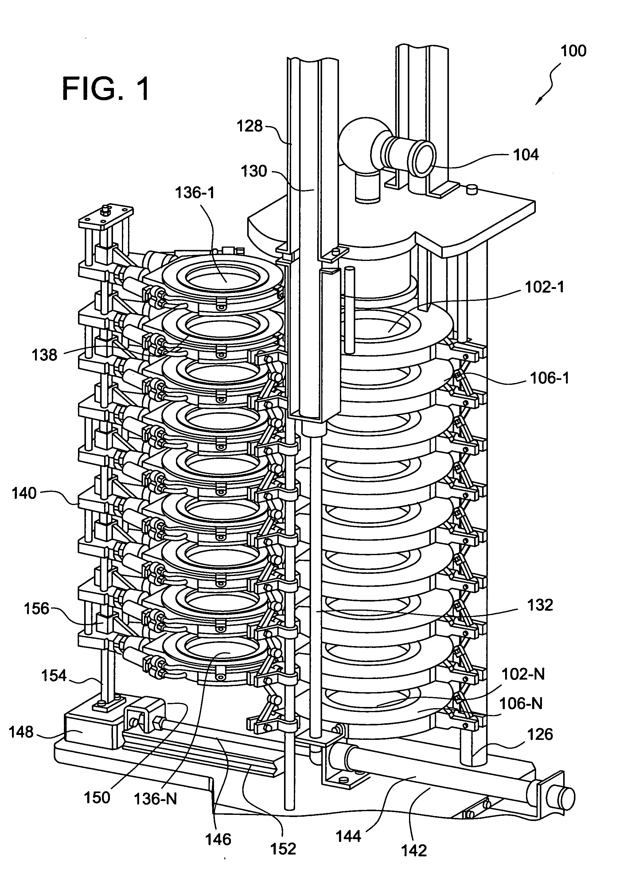
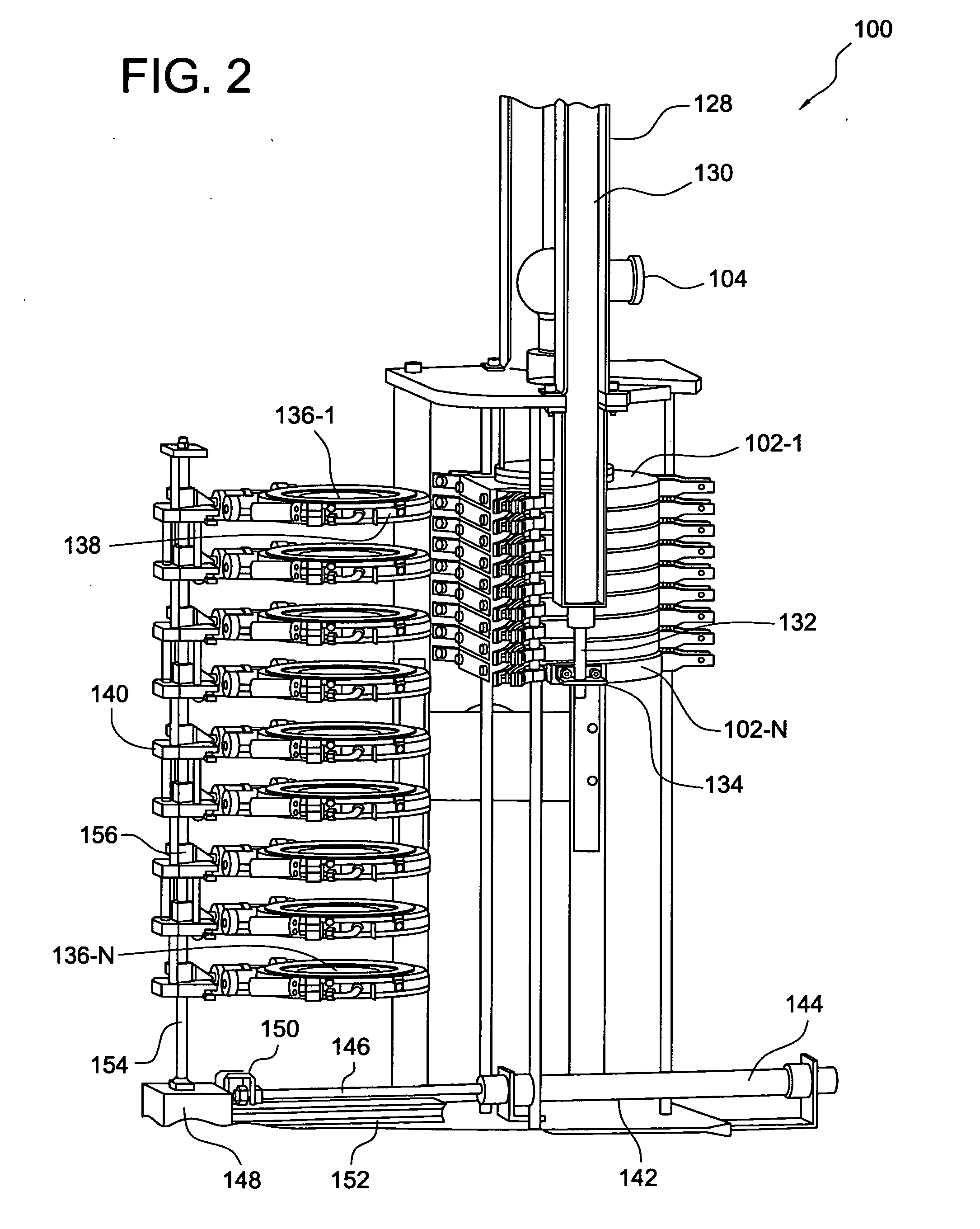
[0029]Referring now to the drawings, and initially, more particularly to FIGS. 1-8 thereof, while a full and complete disclosure of the basic automated cascade impactor may be found within the aforenoted U.S. Pat. No. 7,926,367, and the aforenoted U.S. patent application Ser. No. 12 / 929,051, which patent and patent application are hereby incorporated by reference, a brief description of the basic automated cascade impactor will first be provided for continuity purposes with respect to the ensuing detailed description of the present invention forming the basis for this continuation-in-part (CIP) patent application. More particularly, the basic automated cascade impactor is generally indicated by the reference character 100 and, as has been noted, is used to conduct dose determinations. The basic automated cascade impactor 100 is seen to comprise a vertically oriented stacked array of a plurality of impactor stages 102-1 through 102-N, and an entry throat 104 is operatively connected ...


PUM


Abstract

An automated cascade impactor is disclosed and comprises a vertical array of a plurality of impactor stages, and a vertical array of isolation stages, wherein the vertical array of the isolation stages comprises pairs of isolation stages between which impactor plates, removed from respective ones of the impactor stages are effectively sandwiched between each pair of isolation stages. Still further, each compactor stage is likewise sandwiched between and upper and a lower pair of the isolation stages.

Description

CROSS-REFERENCE TO RELATED PATENT APPLICATIONS[0001]This patent application is a Continuation-in-Part of U.S. patent application Ser. No. 12 / 929,051, which was filed on Dec. 27, 2010, which is entitled AUTOMATED CASCADE IMPACTOR, and which is a continuation patent application of U.S. patent application Ser. No. 12 / 247,546 which was filed on Oct. 8, 2008, which is entitled AUTOMATED CASCADE IMPACTOR, which is now U.S. Pat. No. 7,926,367, and which is based upon International Patent Application Serial Number PCT / US2007 / 008924 which was filed on Apr. 10, 2007, which is entitled AUTOMATED CASCADE IMPACTOR, and which is based upon U.S. Provisional Patent Application Ser. No. 60 / 744,663 which was filed on Apr. 11, 2006 and which is entitled AUTOMATED CASCADE IMPACTOR.FIELD OF THE INVENTION[0002]The present invention relates generally to an automated cascade impactor, and more particularly to an automated cascade impactor which comprises a plurality of impactor stages disposed within a ver...

Claims


Application Information

Patent Timeline
IPC IPC(8): G01N1/22
CPCG01N1/2208G01N15/0255G01N2015/0261
Inventor MAHESHWARI, KRISHNAMAHESHWARI, RAJESH
Owner LAB AUTOMATE TECH
Why Eureka
Try Eureka