cascade impactor

An impactor, cascading technology, applied in the direction of machines/engines, chemical instruments and methods, separation methods, etc., can solve problems such as particle or droplet deposition

Active Publication Date: 2019-11-05
德国保利达塑料有限两合公司
View PDF4 Cites 0 Cited by
  • Summary
  • Abstract
  • Description
  • Claims
  • Application Information

AI Technical Summary

Problems solved by technology

While fine loads follow the flow at low gas velocities, larger particles or droplets deposit on the filter

Method used


Image

  • cascade impactor

Examples


Embodiment Construction

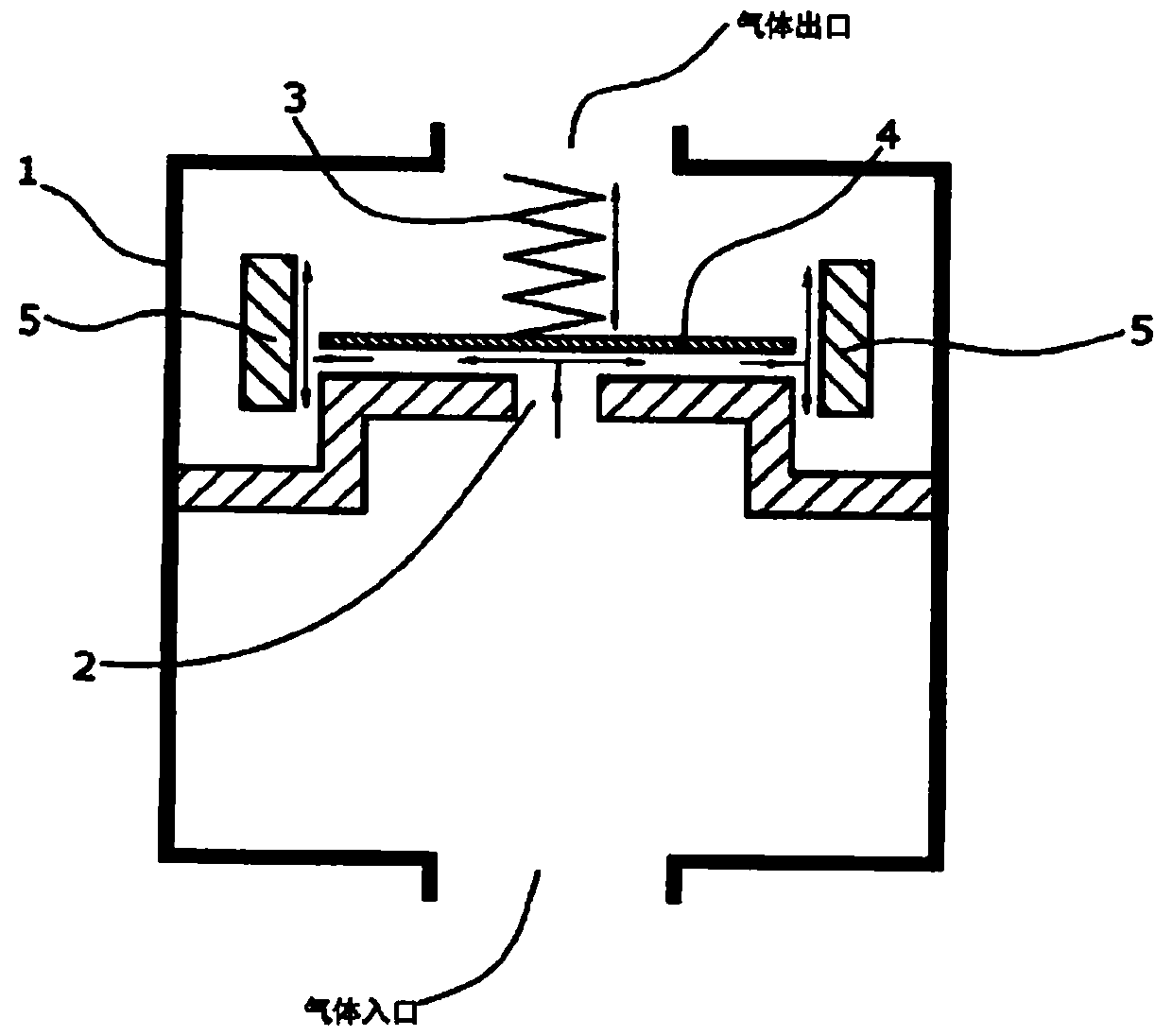
[0011] In a preferred embodiment of the invention, the cascade impactor consists only of the first and second stages. Although basically there can be several impingement stages, in the vast majority of cases, thanks to the invention, the above mentioned two stages are sufficient to remove a sufficient amount of liquid droplets or solid particles from the gas flow.

[0012] The angle at which the baffle surfaces are arranged relative to each other can be varied arbitrarily. However, the closer the angle is to 90°, the higher the separation performance. It is therefore particularly preferred according to the invention if the baffle surfaces of the first and second baffles 4 , 5 are at an angle of 60° to 120°, in particular 85° to 95°, relative to each other. Even more preferably according to the invention, the baffle surfaces of the first and second baffles 4, 5 are at an angle of 90° to each other. Naturally, the same applies to further subsequent baffles, if required.

[00...


PUM


Abstract

The invention relates to a cascade impactor having a first stage comprising a plate (2) with fixed bores as gas inlet and at least a first impact wall (4) with a variable distance from the plate (2) as well as at least a second stage having a fixed second impact wall (5), which is arranged in the flow direction downstream of the first impact wall (4).

Description

technical field [0001] The invention relates to a cascade impactor with multiple stages. Background technique [0002] A cascade impactor is a series connection of nozzle plates. A stepwise reduction in nozzle diameter generally results in an increase in gas velocity. Between the individual nozzle plates there are baffles covered with filter discs. The gas stream laden with solids (particles) or liquid impinges on the filter and is deflected there. While fine loads follow the flow at low gas velocities, larger particles or droplets deposit on the filter. The increasing gas velocity from cascade to cascade thereby separates individual particles or liquid fractions. Cascade impactors are also ready for use in hot and chemically aggressive gases. [0003] EP 2 378 090 A1 relates to an oil mist separator (1) for a crankcase ventilation system. It comprises a first separator unit (2) having at least one filter body (10) arranged in the blowby gas path (11) in such a way tha...

Claims


Application Information

Patent Timeline
Patent Type & Authority Patents(China)
IPC IPC(8): B01D45/08F01M13/04F02M35/022
CPCB01D45/08F01M13/04F01M2013/0433F02M35/0226
Inventor 汉斯·詹森克里斯蒂安·梅勒克里斯托夫·立森
Owner 德国保利达塑料有限两合公司
Why Eureka
Try Eureka