
Internal combustion engine and supplying oil path structure for hydraulic clutch in internal combustion engine

Active Publication Date: 2012-10-04
HONDA MOTOR CO LTD
View PDF5 Cites 13 Cited by
  • Summary
  • Abstract
  • Description
  • Claims
  • Application Information

AI Technical Summary

Benefits of technology

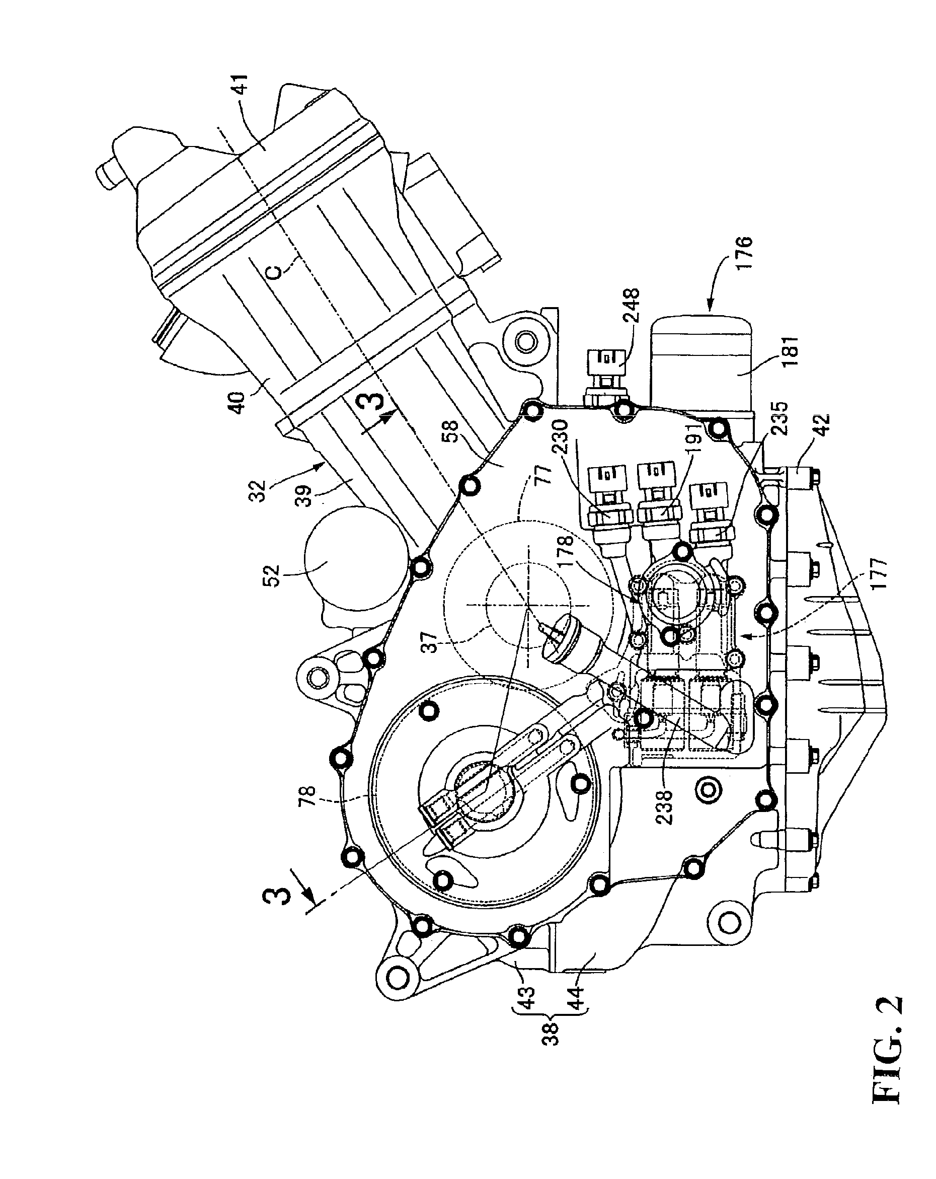
[0030]According to an embodiment of the present invention, since the plural clutch oil pressure sensors are disposed in the proximity of and in parallel to each other while the axial directions thereof are directed in the forward and backward direction, the plural clutch oil pressure sensors can be disposed efficiently and compactly with the directions thereof lined up with each other, and increase in size of the internal combustion engine can be avoided.
[0031]According to an embodiment of the present invention, the oil filter having the cylindrical filter case is disposed such that the axial line of the filter case is directed in the direction crossing with the longitudinal directions of the clutch oil pressure sensors and the oil filter is displaced forwardly or backwardly with respect to the clutch oil pressure sensors. Therefore, the oil filter and the clutch oil pressure sensors can be disposed in a forwardly or backwardly displaced relationship such that they do not overlap with each other in the leftward and rightward direction of the engine main body. Consequently, increase in size of the internal combustion engine in the leftward and rightward direction can be suppressed.
[0032]According to an embodiment of the present invention, since the clutch oil pressure sensors in pair and the oil filter oil pressure sensor are disposed in parallel to each other, the oil filter oil pressure sensor can be disposed efficiently and compactly in addition to the clutch oil pressure sensors.
[0033]According to an embodiment of the present invention, since the outer end of the filter case is disposed outwardly with respect to the outer end of the oil filter oil pressure sensor, when the saddle type vehicle falls down, the oil filter oil pressure sensor can be protected by the outer end of the filter case.
[0034]According to an embodiment of the present invention, since the projection which projects outwardly sidewardly with respect to the oil pressure sensor positioned lowest from among the clutch oil pressure sensors in pair and the oil filter oil pressure sensor is provided in a projecting manner, when the saddle type vehicle falls down, the oil pressure sensor positioned lowermost can be protected by the projection.
[0035]According to an embodiment of the present invention, since the level gage insertion tube which is swollen sidewardly from the engine main body is disposed rearwardly with respect to the oil filter, it is possible to prevent increase in size of the internal combustion engine in the leftward and rightward direction by disposing the level gage insertion tube making use of the dead space around the oil filter.

Problems solved by technology

However, in an internal combustion engine which includes a plurality of hydraulic clutches, in order to control connection / disconnection of the hydraulic clutches, a plurality of oil pressure sensors individually corresponding to the hydraulic clutches are required, and if it is attempted to provide the oil pressure sensors along oil paths disposed in different directions from each other, then the space necessary for the disposition of the oil pressure sensors becomes great.
Therefore, the cover member has an increased size, which gives rise to increase in size of the internal combustion engine.

Method used


Image

  • Internal combustion engine and supplying oil path structure for hydraulic clutch in internal combustion engine
  • Internal combustion engine and supplying oil path structure for hydraulic clutch in internal combustion engine
  • Internal combustion engine and supplying oil path structure for hydraulic clutch in internal combustion engine

Examples


Embodiment Construction

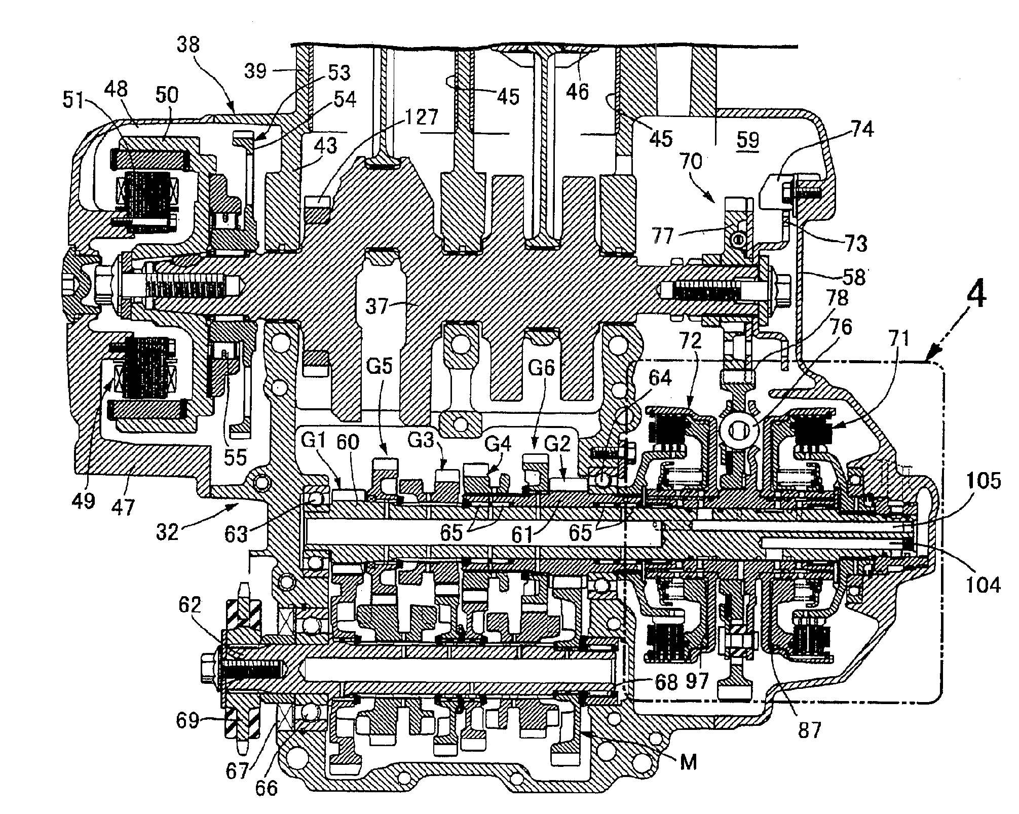
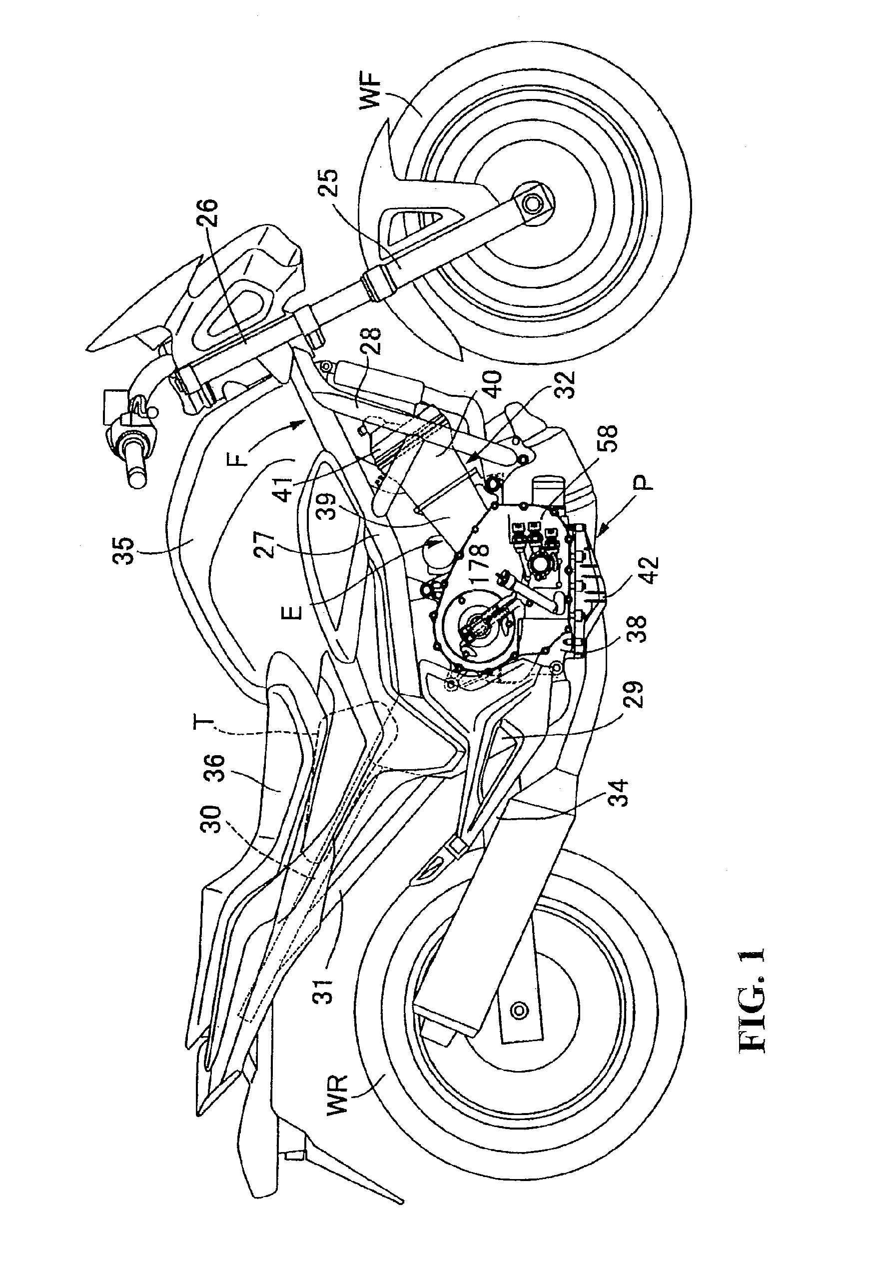
[0069]An embodiment of the present invention is described with reference to FIGS. 1 to 20 of the accompanying drawings. Referring first to FIG. 1, a vehicle body frame F of a motorcycle which is a saddle type vehicle includes a head pipe 26 for supporting a front fork 25, on which a front wheel WF is supported for rotation, for steering movement, a pair of left and right main frames 27, . . . extending rearwardly downwards from the head pipe 26, a pair of left and right down frames 28 . . . extending rearwardly downwards more steeply than the main frames 27, . . . , a pair of left and right center frames 29, . . . extending downwardly from a rear end of the main frames 27, . . . , a pair of left and right seat rails 30, . . . extending rearwardly upwards from an upper portion of the center frames 29, . . . , and rear frames 31, . . . interconnecting intermediate portions of the center frames 29, . . . and rear portions of the seat rails 30, . . . .

[0070]In a region defined by the ma...


PUM


Abstract

An internal combustion engine is provided with a plurality of hydraulic clutches, a plurality of hydraulic controlling valves for individually controlling the oil pressure for the hydraulic clutches, and a plurality of clutch oil pressure sensors for individually detecting the controlling oil pressure of controlling oil supplying paths interconnecting the hydraulic controlling valves and the hydraulic clutches. The oil pressure sensors individually correspond to the hydraulic clutches compactly, thereby to preventing an increase in size. The clutch oil pressure sensors are provided on an engine main body so as to be disposed in the proximity of and in parallel to each other while axial directions thereof are directed in a forward and backward direction of a saddle type vehicle in a state in which the engine main body is mounted on the saddle type vehicle.

Description

CROSS-REFERENCE TO RELATED APPLICATION[0001]The present application claims priority under 35 U.S.C. §119 to Japanese Patent Applications No. 2011-080682 and 2011-080683, both filed on Mar. 31, 2011, the entire contents of which are hereby incorporated by reference.BACKGROUND OF THE INVENTION[0002]1. Field of the Invention[0003]This invention relates to an internal combustion engine which includes a plurality of hydraulic clutches, a plurality of hydraulic controlling valves for individually controlling the oil pressure for the hydraulic clutches, and a plurality of clutch oil pressure sensors for individually detecting the controlling oil pressure of controlling oil supplying paths interconnecting the hydraulic controlling valves and the hydraulic clutches. The hydraulic (oil pressure) controlling valves individually correspond to the hydraulic clutches and each has a valve housing and a valve body accommodated in the valve housing attached to a cover member. The cover member config...

Claims


Application Information

Patent Timeline
IPC IPC(8): F16D25/10
CPCF01M1/16F16H3/006F16D48/0206F16D2300/26F16D2021/0661F16D2300/18F16D2021/0623F16D2048/0281F16D2500/1117F16D2500/3058F16D25/10
Inventor MITSUBORI, TOSHIMASANAITO, MASAZUMI
Owner HONDA MOTOR CO LTD
Learn More