Automatic Determination of Compliance of a Part with a Reference Drawing

a technology of reference drawing and automatic determination, applied in the field of automatic determination of compliance of parts with reference drawing, can solve problems such as inherent disadvantages that this may entail

Active Publication Date: 2012-10-04
VISIONX INC
View PDF2 Cites 18 Cited by
  • Summary
  • Abstract
  • Description
  • Claims
  • Application Information

AI Technical Summary

Benefits of technology

[0045]e. comparing the deviation to a predetermined tolerance in order to de...

Problems solved by technology

In the past, a comparison of the part to engineering drawings has been done manually or through vis...

Method used


Image

  • Automatic Determination of Compliance of a Part with a Reference Drawing
  • Automatic Determination of Compliance of a Part with a Reference Drawing
  • Automatic Determination of Compliance of a Part with a Reference Drawing

Examples


Embodiment Construction

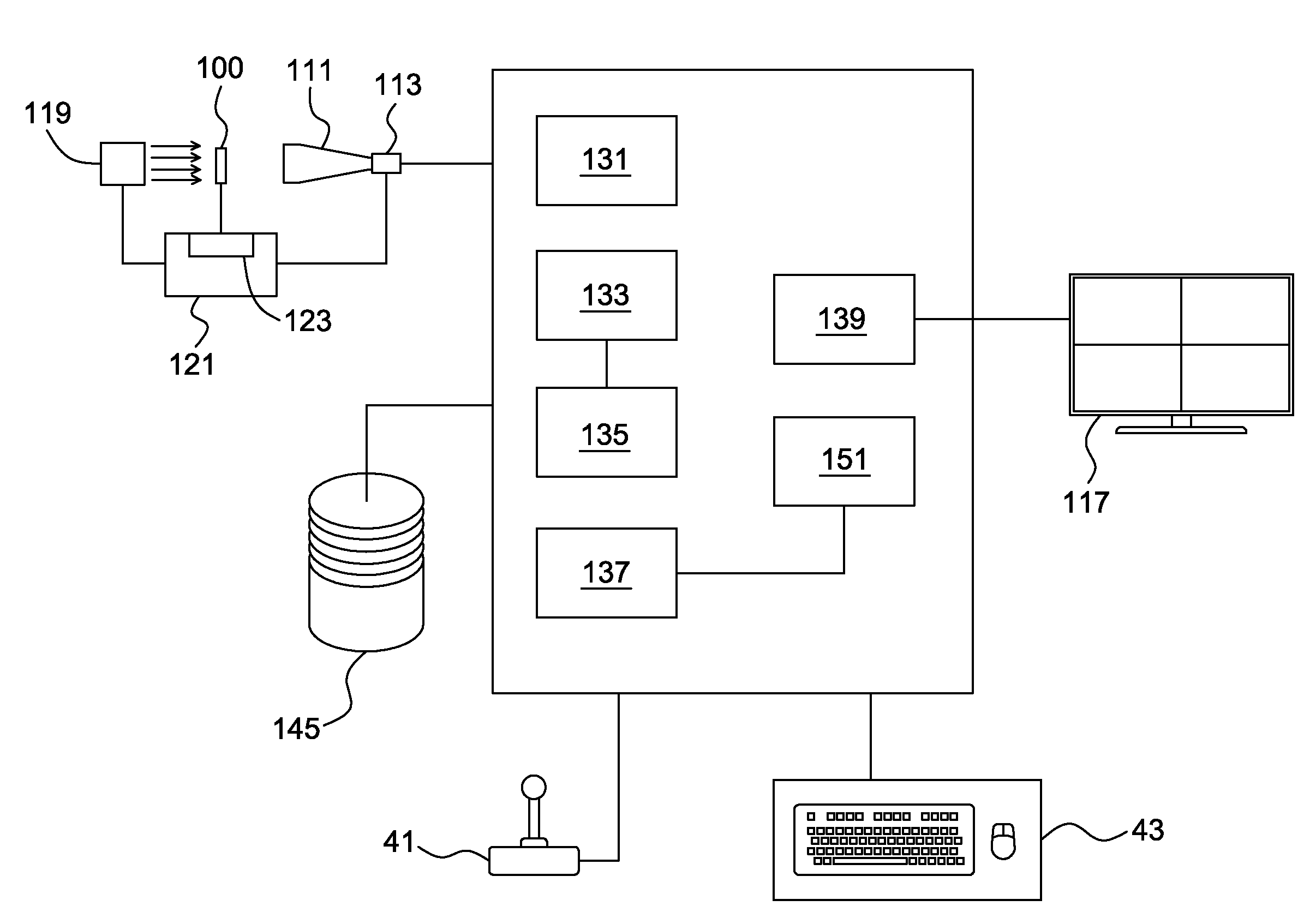
[0062]The present invention finds particular use in an imaging system that is capable of overlaying a part's appropriately scaled, translated and rotated CAD data on top of the live or still video image of the part. Of course, the present invention can be used in all computerized imaging systems.

[0063]In a preferred embodiment, the system of the present invention includes a lens 111, a digital camera 113 and a computer, or other appropriate data processing system, 115 running the appropriate hardware and software to interface with the camera

[0064]Since such a system is designed to study both small and large items, the system preferable includes one or more monitors 117. A preferred implementation provides for multiple monitors which allows the high-resolution image produced by the camera to be displayed fully (i.e. in 1:1 resolution on the bank of monitors, so that every pixel coming from the camera corresponds to a pixel on the bank of monitors, and allows for room for other window...


PUM


Abstract

A system for visually comparing a part to a drawing of said part in computer memory or on a screen is provided. The system includes a camera for capturing either a single image or an image stream of the part, a computing module for receiving the image or image stream, for obtaining, scaling, positioning and displaying the drawing of the part on a display unit and for overlaying the drawing on the image or image stream. The system determines if the part is manufactured within predefined tolerances at least one control section. In use, a user defines at least one control section and the system performs a CAD-space to image-space transformation of each control section. A deviation between the CAD drawing and the part at each control section is calculated, and this deviation is indicated to the user. The deviation is compared to a predetermined tolerance in order to determine if the part at each control section is within the predetermined tolerance; and a pass/fail indication is determined based on the comparison. For more complex shapes, a user can select an entire geometrical shape, and the system automatically determines a plurality of control sections within the geometric shape, in order to provide the user with a shape pass/fail indication.

Description

FIELD OF THE INVENTION[0001]The present invention relates to a system and method for automatically determining if a part is within a predetermined tolerance, either in a control section, or for the whole part.BACKGROUND OF THE INVENTION[0002]In manufacturing processes, it is almost always necessary to perform quality control on a part so manufactured. In some cases, this quality control will permit the manufacturer to sell the part for a better price if the part is within tighter tolerances. Additionally, in some industries such as the aerospace industry, or the electronics industry, parts will be rejected if they are not manufactured to strict tolerances.[0003]In the past, a comparison of the part to engineering drawings has been done manually or through vision systems, but using a paper copy of the drawings, with the inherent disadvantages that this may entail.[0004]The Assignee of the present application has filed International Patent Application No. PCT / CA2010 / 000295 (published ...

Claims


Application Information

Patent Timeline
IPC IPC(8): H04N5/228G06K9/68
CPCG06T7/001G06T2207/30164G06T2207/10016
Inventor BEAUCHEMIN, PATRICK
Owner VISIONX INC
Why Eureka
Try Eureka