
Cutting apparatus, cutting data processing device and cutting control program therefor

a technology of cutting data processing and cutting control, which is applied in the field of cutting apparatuses, can solve the problems of troublesome removal of an entire unnecessary part of the sheet, increase in the amount of waste sheet, etc., and achieve the effect of reducing the waste of the obj

Active Publication Date: 2012-10-04
BROTHER KOGYO KK
View PDF6 Cites 15 Cited by
  • Summary
  • Abstract
  • Description
  • Claims
  • Application Information

AI Technical Summary

Benefits of technology

[0007]Therefore, an object of the disclosure is to provide a cutting apparatus which can reduce an unnecessary part in a postcutting object to be cut thereby to reduce waste of the object, a cutting data processing device for use with the cutting apparatus and a cutting control program on which the cutting apparatus is operable.

Problems solved by technology

However, since the unnecessary part of the sheet is to be disposed of, the user firstly removes the unnecessary part of the sheet to dispose of the unnecessary part even when a small pattern is cut out of a much larger sheet.
This results in an increase in an amount of waste sheet.
Furthermore, it is troublesome to remove an entire unnecessary part of sheet.

Method used


Image

  • Cutting apparatus, cutting data processing device and cutting control program therefor
  • Cutting apparatus, cutting data processing device and cutting control program therefor
  • Cutting apparatus, cutting data processing device and cutting control program therefor

Examples


first embodiment

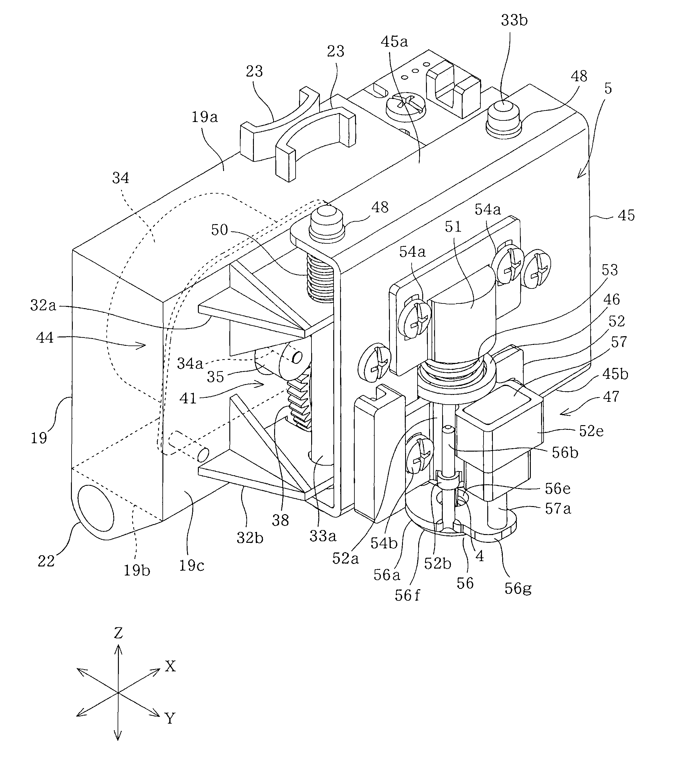
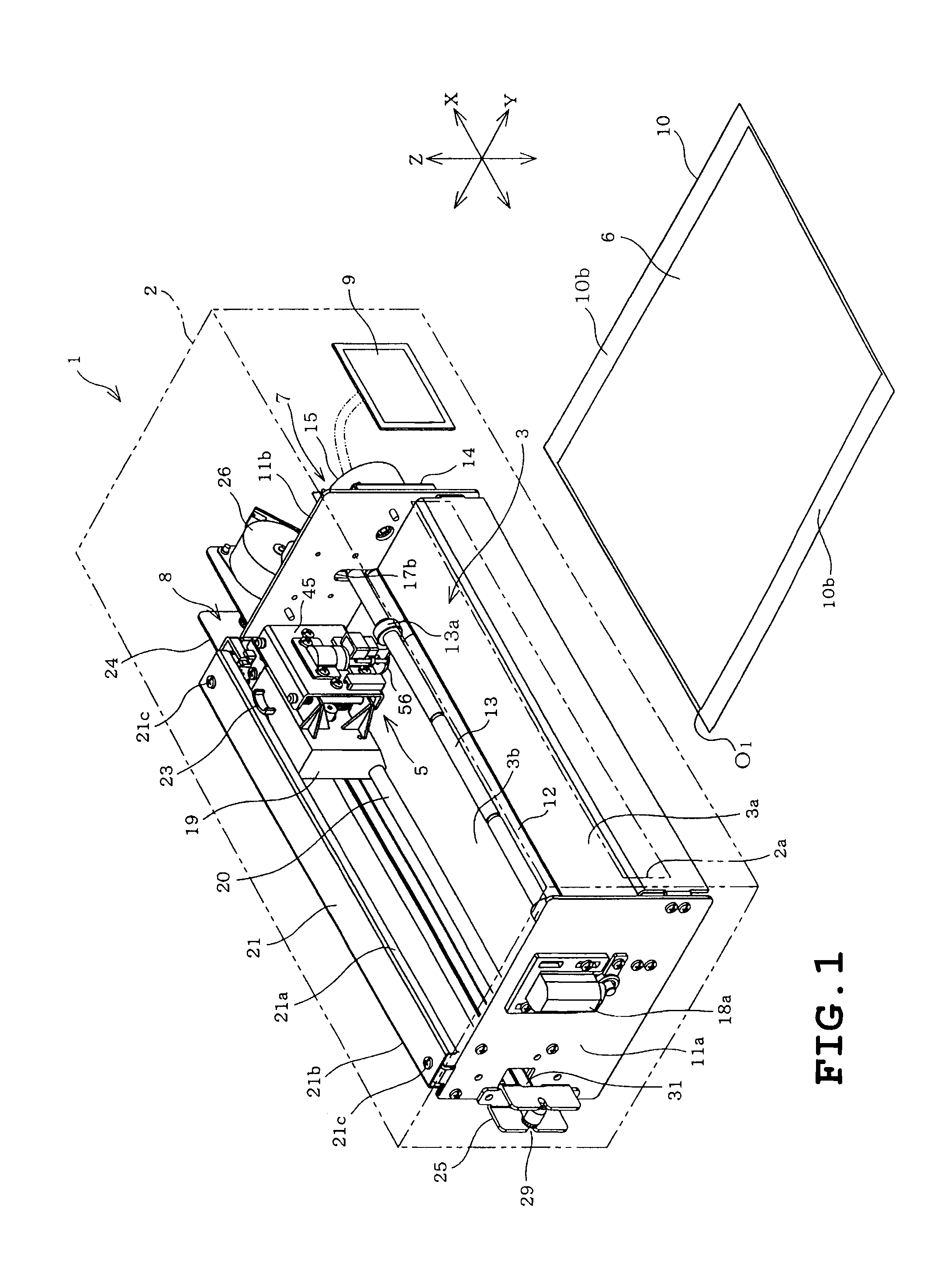
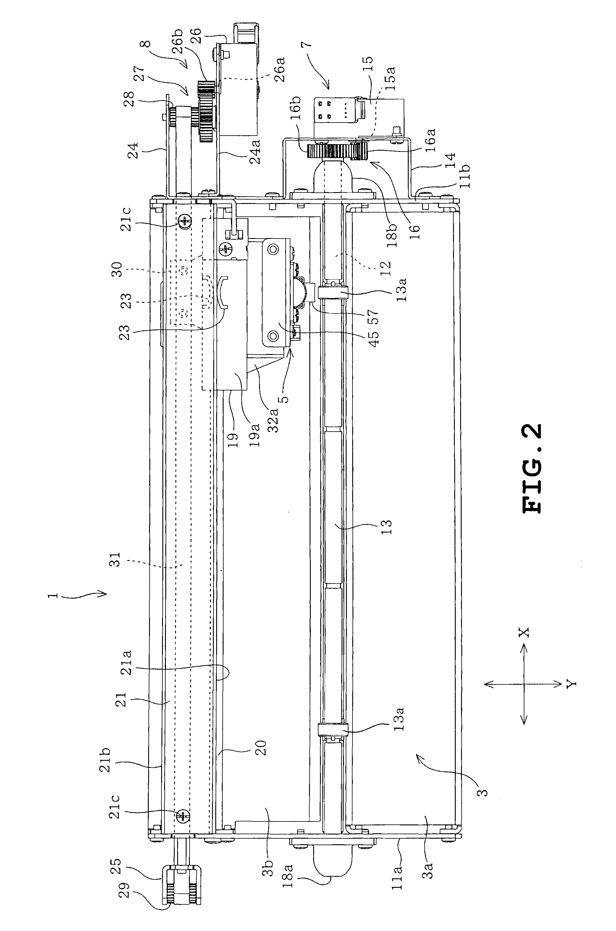
[0039]A first embodiment will be described with reference to FIGS. 1 to 19B. Referring to FIG. 1, a cutting apparatus 1 includes a body cover 2 as a housing, a platen 3 provided in the body cover 2 and a cutter holder 5 also provided in the body cover 2. The cutting apparatus 1 also includes first and second moving units 7 and 8 for moving a cutter 4 (see FIG. 5) of the cutter holder 5 and an object 6 to be cut, relative to each other. The body cover 2 is formed into the shape of a horizontally long rectangular box and has a front formed with a horizontally long opening 2a which is provided for setting a holding sheet 10 holding the object 6. In the following description, the side where the user who operates the cutting apparatus 1 stands will be referred to as “front” and the opposite side will be referred to as “back.” The front-back direction thereof will be referred to as “Y direction.” The right-left direction perpendicular to the Y direction will be referred to as “X direction...

second embodiment

[0092]FIGS. 20 to 23 illustrate a second embodiment. Only the difference between the first and second embodiments will be described. As understood from the comparison of FIG. 21A with FIG. 15A, the sizes of the patterns A to C slightly differ from one another. However, the same reference symbols are applied to the patterns in the second embodiment as those in the first embodiment for the sake of easiness in understanding. Identical or similar parts other than the aforementioned patterns in the second embodiment are labeled by the same reference symbols as those in the first embodiment.

[0093]In the cutting apparatus 1 of the second embodiment, the cutting data processing program is executed to generate boundary cutting data for cutting, for example, only the region hatched in FIG. 20 as an unnecessary portion. The boundary cutting data is related to a boundary L110 that is set a predetermined distance outside a rectangular frame F110 (see FIG. 21A; and on the downside in the figure, ...

third embodiment

[0114]FIGS. 24 and 25 illustrate a third embodiment. Only the difference between the second and third embodiments will be described. Identical or similar parts in the third embodiment are labeled by the same reference symbols as those in the second embodiment.

[0115]In the third embodiment, when the pattern A is cut out of the object 6 as shown in FIG. 24, the sizes of the unused regions are compared with each other between a case where the used region and the unused region are divided by a boundary L131 extending in the first or Y direction and a case where the used region and the unused region are divided by a boundary L132 extending in the second or X direction. As a result, the boundary which divides so that the unused region is increased is selected and set. The size of the unused region is represented as an area thereof in the third embodiment.

[0116]The external memory 64 in the third embodiment stores minimum reference values γ1 and γ2 (see FIGS. 24 and 25) which serve as refe...


PUM

PropertyMeasurementUnit
Sizeaaaaaaaaaa
Shapeaaaaaaaaaa
Distanceaaaaaaaaaa

Abstract

A cutting apparatus is disclosed in which a cutting blade and an object to be cut are moved relative to each other so that a desired pattern is cutout of the object. The cutting apparatus includes an arranging unit arranging the pattern in a cut-allowable region of the object, a frame setting unit setting a minimum boundary frame which is polygonal or curved in shape and includes a contour of the pattern arranged by the arranging unit, and a cutting data generating unit generating outer line cutting data for cutting an outer line dividing a first region near the pattern within the cut-allowable region and a second region other than the first region, outside the boundary frame, based on the boundary frame. The pattern and the outer line are cut out of the object based on pattern cutting data for cutting the pattern and the outer line cutting data.

Description

CROSS-REFERENCE TO RELATED APPLICATIONS[0001]This application is based upon and claims the benefit of priority from the prior Japanese Patent Application Nos. 2011-075582 filed on Mar. 30, 2011 and 2011-149129 filed on Jul. 5, 2011, the entire contents of which are incorporated herein by reference.BACKGROUND[0002]1. Technical Field[0003]The present disclosure relates to a cutting apparatus in which a cutting blade and an object to be cut are moved relative to each other so that a desired pattern is cut out of the object, a cutting data processing device which processes cutting data for the cutting apparatus and a computer-readable cutting control program on which the cutting apparatus is operable.[0004]2. Related Art[0005]There has conventionally been known a cutting plotter which automatically cuts a sheet such as paper, for example. The sheet is affixed to a base material serving as a holding member having an adhesive layer on a surface thereof. The cutting plotter includes a driv...

Claims


Application Information

Patent Timeline
IPC IPC(8): G06F19/00B26D5/20
CPCB26F1/3813B26D5/005Y10T83/0462Y10T83/0605Y10T83/162
Inventor KAWAGUCHI, YASUHIKONAGAI, MASAHIKONIIZEKI, TOMOYASUNAKAMURA, YOSHINORIHASEGAWA, KATSUHISA
Owner BROTHER KOGYO KK
Learn More