Spacer Piece and Section Piece for Slide Rail of Automotive Vehicle Seat
Active Publication Date: 2012-10-11
FAURECIA
View PDF20 Cites 16 Cited by
Summary
Abstract
Description
Claims
Application Information
AI Technical Summary
This helps you quickly interpret patents by identifying the three key elements:
Problems solved by technology
Method used
Benefits of technology
Benefits of technology
[0011]the base portion of the section piece comprises a bearing surface facing towards the inside of the U shape, the first and second inner surfaces each being connected to the bearing surface by a curved surface, the reinforcing spacer piece additionally comprising protuberances projecting outwards from the body in the transverse direction, facing the curved surfaces; said protuberances thereby limiting the noise in the presence of most vibration stresses;
[0013]the reinforcing spacer piece additionally comprises transverse walls such that the longitudinal walls and the transverse walls form cells, thus the energy absorbed in case of impact can be increased;
Problems solved by technology
The slide rails and the section pieces in question are not optimal for absorbing energy during an impact nor with respect to the noises which may be generated in the presence of certain vibration stresses.
Method used
Image
Click on the blue label to locate the original text in one second.
Reading with bidirectional positioning of images and text.
Examples
first embodiment
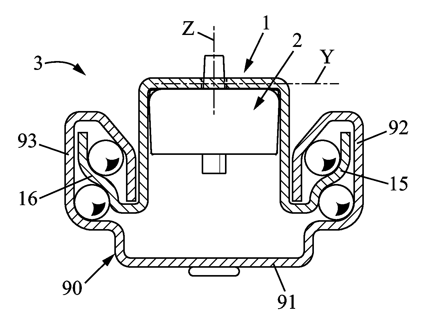
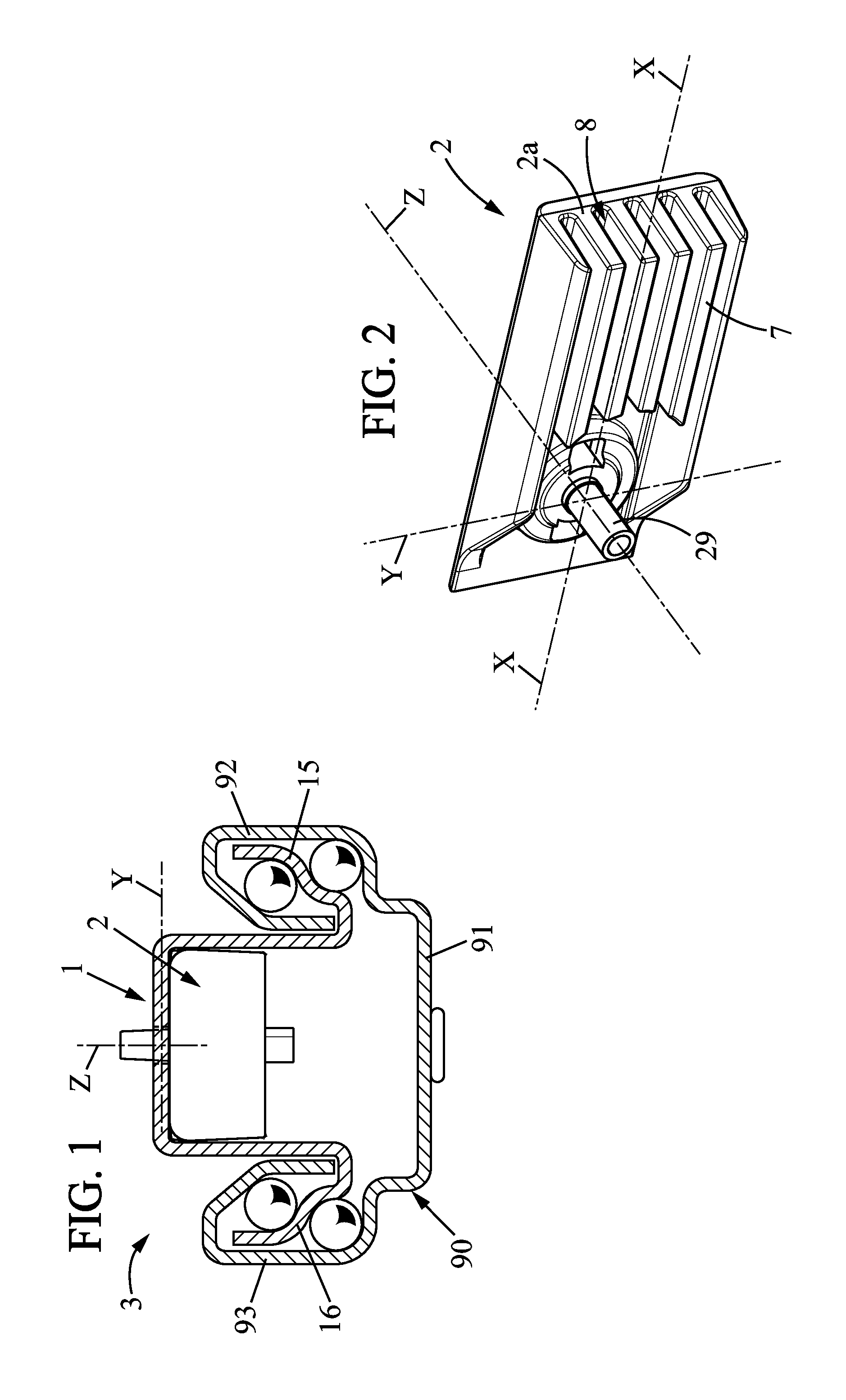
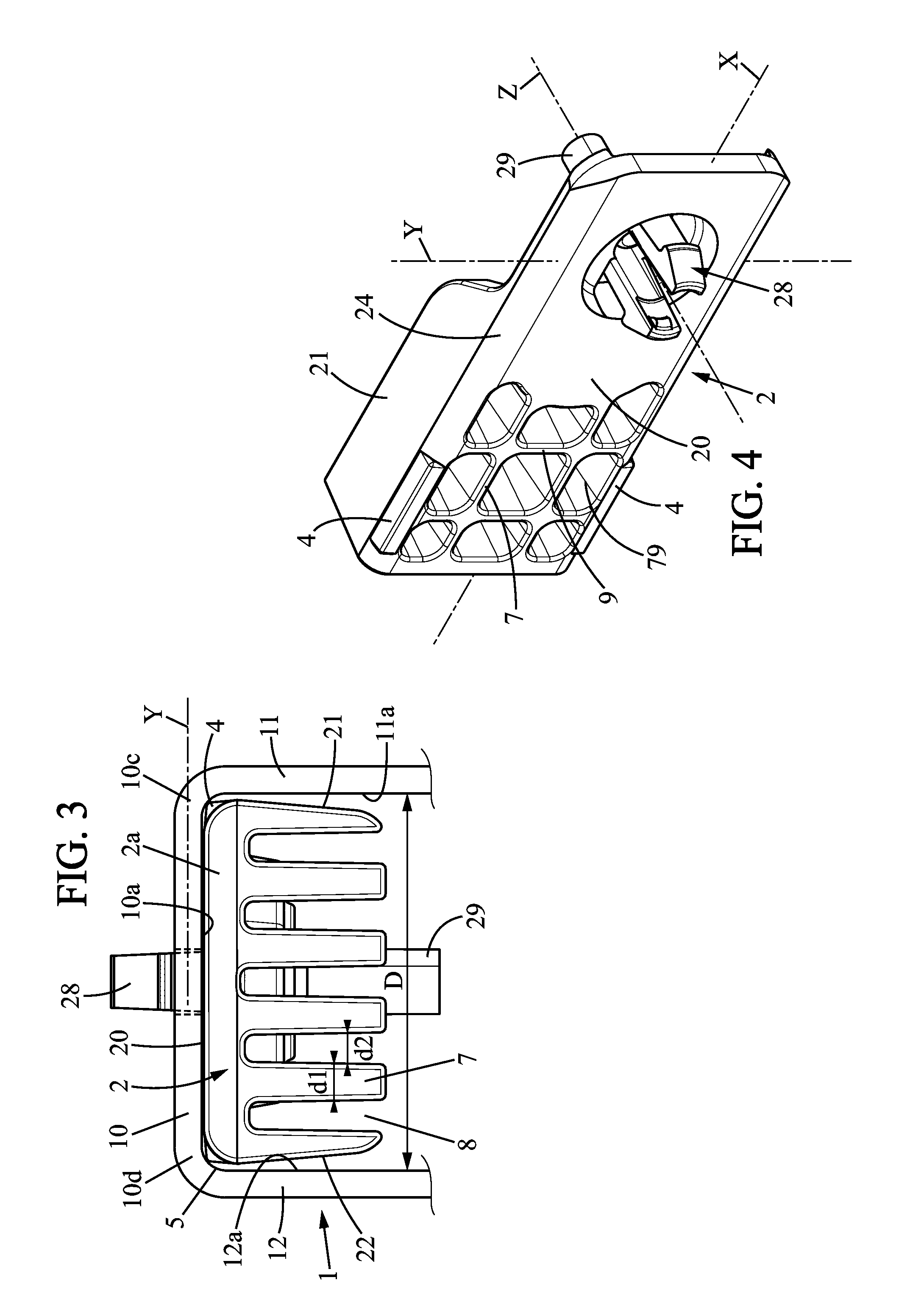
[0036]In the invention (FIGS. 1 to 3), the reinforcing spacer piece 2 comprises longitudinal walls (or ribs) 7 extending in a plane XZ from the body 2a. These longitudinal ribs 7 are separated by recessed spaces 8, and as a result a transverse section in a plane perpendicular to the longitudinal axis X, as illustrated in FIG. 3, comprises an alternating succession of wall portions 7 and recessed spaces 8 which has a rake-like appearance.
[0037]Advantageously, according to the invention, said wall portions 7 each have a first transverse dimension d1 and the recessed spaces 8 each have a second transverse dimension d2 that is similar to the first transverse dimension d1. In this manner, in case of an impact, the compression is limited to about half the width of the body 2a of the spacer piece 2.
[0038]Without exceeding the scope of the invention, the number of ribs 7 as well as their respective thickness relative to the recessed spaces 8 could be different and be chosen to optimize impa...
second embodiment
[0039]In the invention (FIGS. 1 and 4 to 6), the reinforcing spacer piece 2 additionally comprises transverse walls 9, so that the longitudinal walls 7 and the transverse walls 9 together form cells 79. This increases the transverse rigidity as well as the energy absorbed in case of impact.
[0040]One will note, as illustrated in FIG. 5, that a transverse cross-section, in a plane perpendicular to the longitudinal axis X, shows an alternating succession of portions of said walls 7 and recessed spaces 8 as was seen in the first embodiment.
[0041]The following elements apply to either of the two embodiments.
[0042]In addition, the reinforcing spacer piece 2 may comprise protuberances 4 which project outwards from the body in the transverse direction Y, facing the curved surfaces 5.
[0043]More specifically, the reinforcing spacer piece 2 may comprise a supporting surface 20, side edges 21,22, and rounded shapes 24,25 connecting the side edges and the supporting surface, the protuberances 4 ...
PUM
Abstract
Reinforced section piece comprising a metal section piece and a reinforcing spacer piece, said section piece having a generally U-shaped cross-section with a base portion, said section piece comprising side wings extending perpendicularly on each side from the transverse ends of the base portion, with inner surfaces facing each other at an inside distance, the reinforcing spacer piece comprising a body having a width that is slightly less than the inner distance, and being configured to prevent the lessening of the distance between the two side wings, the reinforcing spacer piece additionally comprising protuberances projecting outwards from the body in the transverse direction, facing the curved surfaces of the male section piece.
Description
FIELD OF THE INVENTION[0001]The invention relates to the section pieces used in slide rails for automotive vehicle seats and to the reinforcing spacer pieces used in such slide rails.BACKGROUND OF THE INVENTION[0002]It particularly relates to a reinforcing spacer piece, adapted for assembly between two metal walls of a section piece and configured to limit the compression of said section piece. This reinforcing spacer piece extends longitudinally.[0003]The invention also relates to a reinforced section piece comprising a metal section piece and such a reinforcing spacer piece, said section piece extending longitudinally and having a generally U-shaped cross-section, with a base portion extending substantially in a plane containing the longitudinal direction and a perpendicular transverse direction, said section piece comprising first and second side wings forming said metal walls, extending substantially perpendicularly on each side from the transverse ends of the base portion, the ...
Claims
Application Information
Patent Timeline
Application Date:The date an application was filed.
Publication Date:The date a patent or application was officially published.
First Publication Date:The earliest publication date of a patent with the same application number.
Issue Date:Publication date of the patent grant document.
PCT Entry Date:The Entry date of PCT National Phase.
Estimated Expiry Date:The statutory expiry date of a patent right according to the Patent Law, and it is the longest term of protection that the patent right can achieve without the termination of the patent right due to other reasons(Term extension factor has been taken into account ).
Invalid Date:Actual expiry date is based on effective date or publication date of legal transaction data of invalid patent.

