
Vehicle frame with offset load path to a hinge pillar and rocker

Inactive Publication Date: 2010-10-28
FORD GLOBAL TECH LLC
View PDF22 Cites 14 Cited by
  • Summary
  • Abstract
  • Description
  • Claims
  • Application Information

AI Technical Summary

Benefits of technology

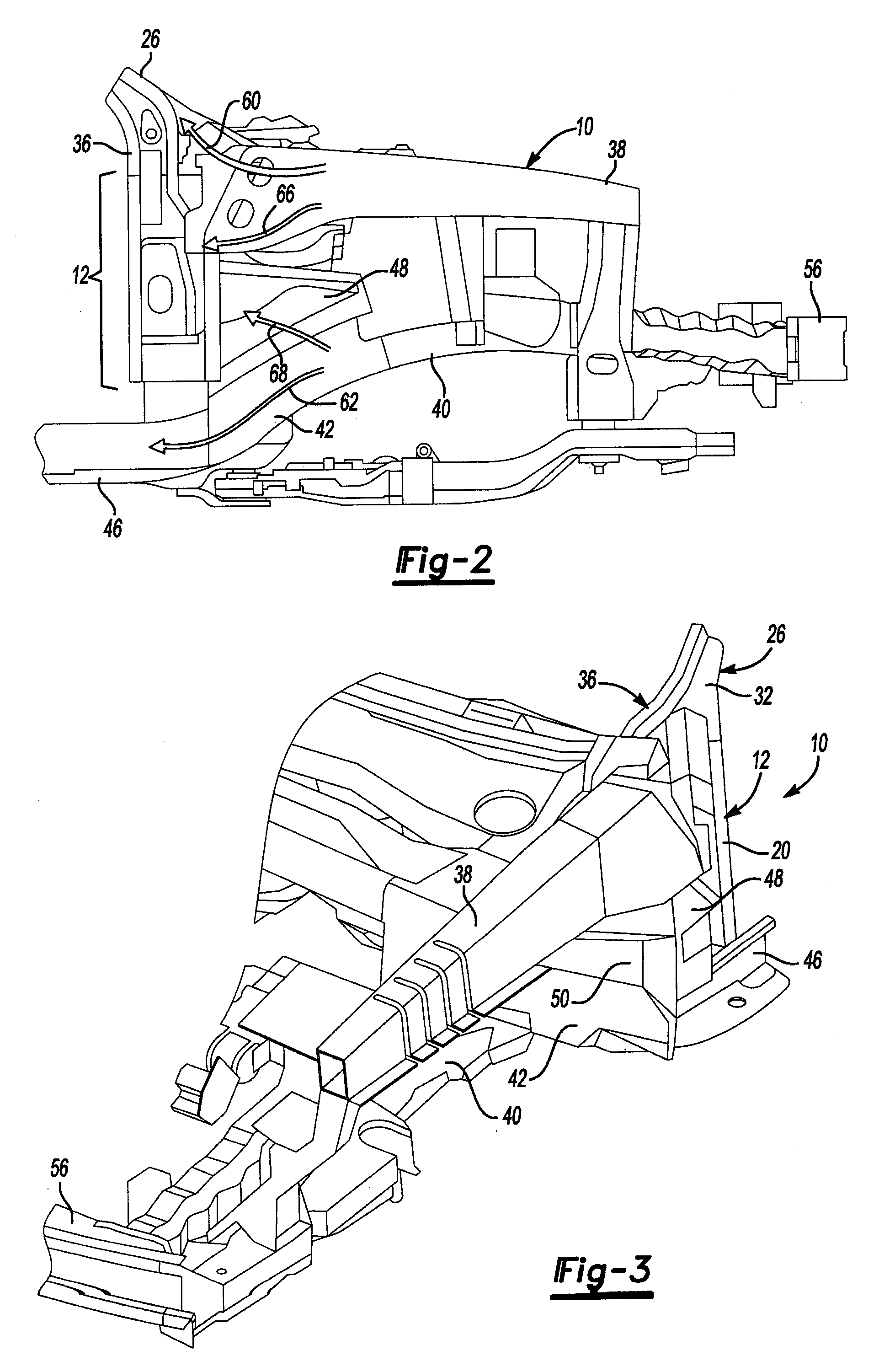
[0012]To increase energy absorption by the back-up rail and improve intrusion map performance, an extension may be provided that is secured to the back up rail and the hinge pillar at a location above the rocker. In addition, forces transmitted along the upper load path may be divided by a fork or other structure to provide a structural load path from the upper rail to the hinge pillar and cowl side inner panel. The reinforced hinge pillar and cowl side inner panel can be tied to the upper front rail and lower front rail to provide a more robust load path for offset loads and also to accommodate multiple load paths.

Problems solved by technology

Hinge pillars do not normally provide the primary support for the front end structure in the event of a front end collision.
The front rail is offset from the rocker and loads applied during a front end collision result in a bending moment located where the back-up rail is connected to the front end of the rocker.
The bending moment reduces vehicle energy absorption and may adversely impact intrusion map performance.

Method used


Image

  • Vehicle frame with offset load path to a hinge pillar and rocker
  • Vehicle frame with offset load path to a hinge pillar and rocker
  • Vehicle frame with offset load path to a hinge pillar and rocker

Examples


Embodiment Construction

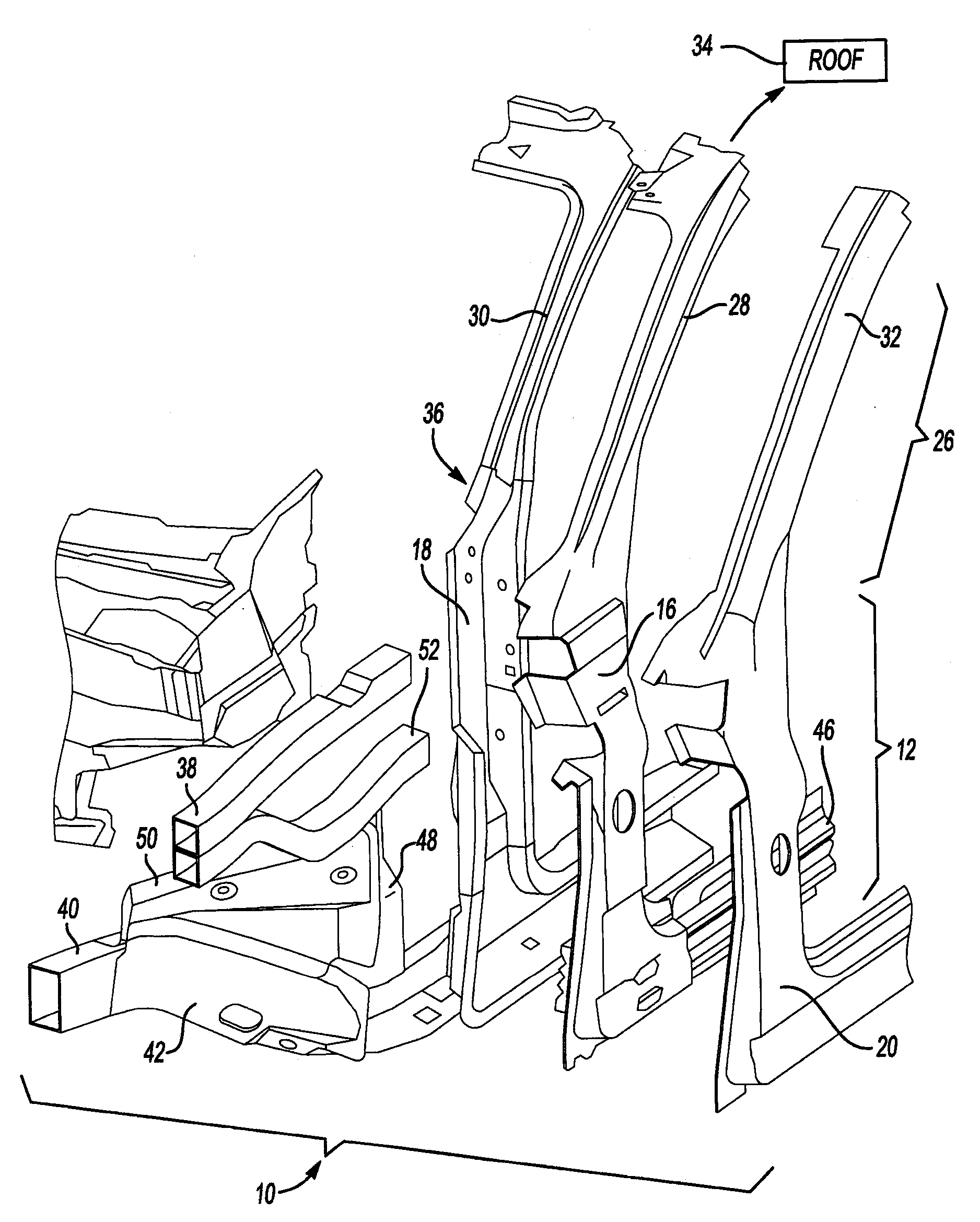
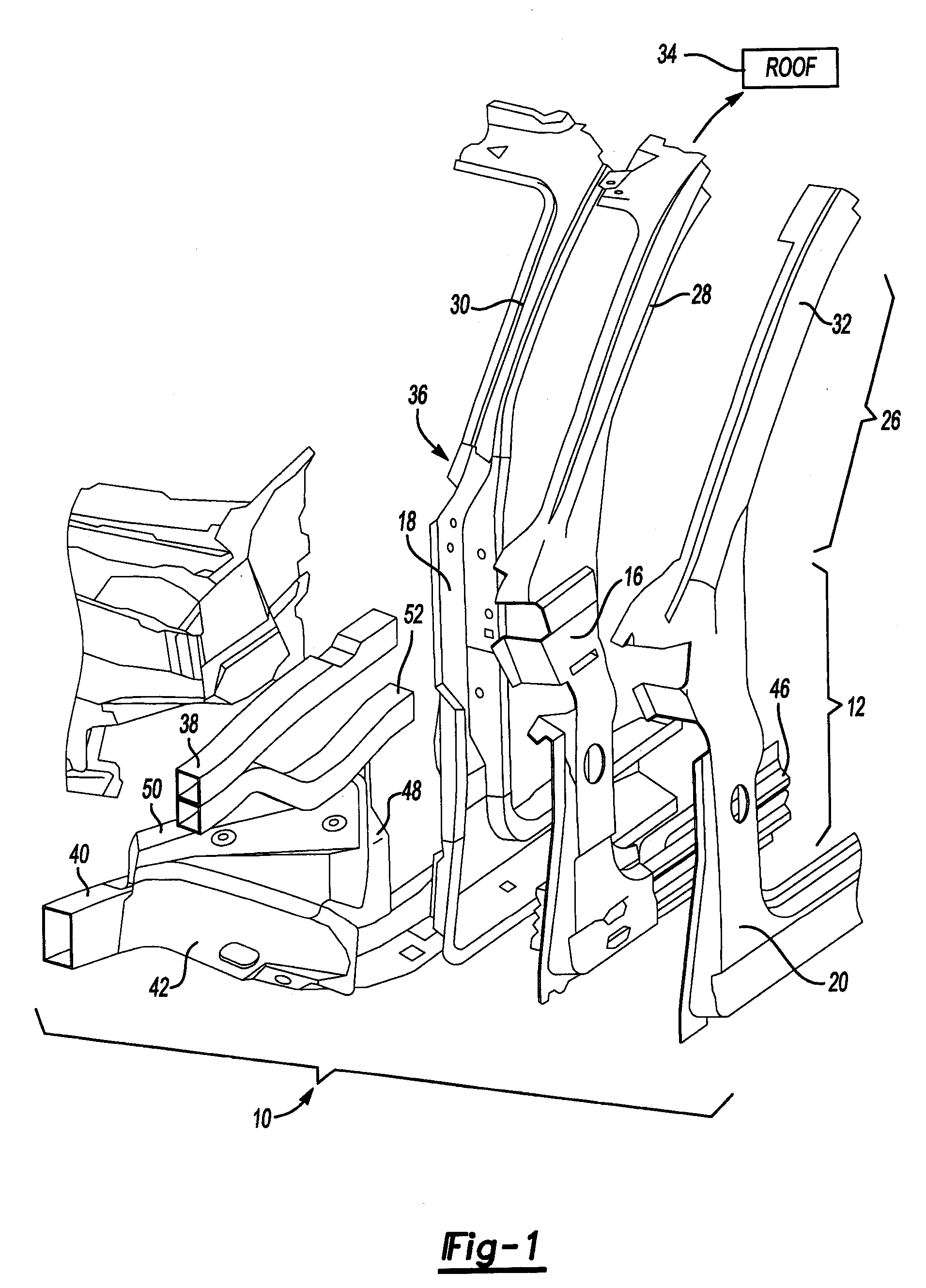
[0017]Referring to FIG. 1, a vehicle frame sub-assembly 10 is shown in an exploded perspective view. The vehicle frame sub-assembly 10 includes a hinge pillar assembly 12. The hinge pillar assembly 12 includes a hinge pillar reinforcement 16 that is attached on its inside to a cowl side inner panel 18. An outer hinge pillar panel 20 is attached over the outer side of the hinge pillar reinforcement 16. The hinge pillar reinforcement 16 and the cowl side inner panel 18 together form a box channel 22. The hinge pillar reinforcement 16 and cowl side inner panel 18 are preferably formed of a dual phase material, such as DP-600, which is a dual phase martensitic steel alloy.

[0018]An A-pillar assembly 26 includes an A-pillar reinforcement 28 that is attached on its inner side to an A-pillar cowl side inner panel 30. An outer A-pillar panel 32 is assembled over the outer side of the A-pillar reinforcement 28 to complete the A-pillar assembly 26. The A-pillar assembly 26 is connected on its ...


PUM


Abstract

A vehicle frame sub-assembly including a hinge pillar assembly and A-pillar assembly. A high strength hinge pillar reinforcement and A-pillar reinforcement are provided to increase the support in roof crush tests. Collision impact loads are transferred through an upper load path, lower load path, upper intermediate load path, and lower intermediate load path. A back-up rail receives loads from the front rail. The back-up rail transfers loads to the rocker and through a back-up rail extension to the hinge pillar assembly. An upper intermediate load path transfers loads from the upper rail through a fork rail to the hinge pillar assembly.

Description

BACKGROUND[0001]1. Field of the Invention[0002]The present invention relates to front end collision load paths defined by the vehicle frame and other support structures.[0003]2. Background Art[0004]Hinge pillars are the part of a vehicle to which vehicle doors are attached by hinges. Hinge pillars do not normally provide the primary support for the front end structure in the event of a front end collision. The primary support for the front end structure is provided by frame members that define a lower load path and an upper load path.[0005]The lower load path and upper load path are defined by the vehicle frame for analysis of collision energy management and the development of passenger compartment intrusion maps. Intrusion maps simulate vehicle energy absorption in response to collision loads. The upper load path transfers forces to the upper structure of the vehicle that includes the roof structure. The lower load path transfers forces to the lower vehicle structure that includes ...

Claims


Application Information

Patent Timeline
IPC IPC(8): B62D25/04B62D23/00
CPCB62D25/04B62D21/152
Inventor BACCOUCHE, MOHAMED R.MOUCH, TIMOTHY ALANKOSTROMINOV, VIKTOR
Owner FORD GLOBAL TECH LLC
Learn More