Curtain airbag system

a curtain airbag and airbag technology, applied in the direction of pedestrian/occupant safety arrangement, vehicular safety arrangement, vehicle components, etc., can solve the problems of difficult use of curtain airbag systems of this type in vehicles with narrow front pillars and unsuitable protection for occupants, and achieve the effect of improving the protection capacity of occupants

Inactive Publication Date: 2012-10-11
TOYOTA JIDOSHA KK
View PDF8 Cites 17 Cited by
  • Summary
  • Abstract
  • Description
  • Claims
  • Application Information

AI Technical Summary

Benefits of technology

[0007]It is an object of the invention to provide a curtain airbag system that is suitably used in a vehicle having narrow front pillars and assures an improved occupant protection capability of protecting an occupant in the event of rollover of the vehicle.
[0009]In the curtain airbag system according to the first aspect of the invention, in the event of a side impact of the vehicle, at least the first deployment portion is deployed with gas supplied thereto, so as to protect the head of an occupant against the side impact. In the event of rollover of the vehicle, on the other hand, the first deployment portion and the second deployment portion are inflated and deployed with gas supplied thereto. The first deployment portion and second deployment portion, when inflated and deployed, restrict outward movement of the head of the occupant in the vehicle width direction, over a wide range in the longitudinal direction of the vehicle. Namely, the head of the occupant is protected in the rollover situation.
[0010]The curtain airbag system, in which the second deployment portion is stored in the roof side portion, can be more suitably used in a vehicle having thin or narrow front pillars, as compared with the arrangement in which the second deployment portion is stored in the front pillar. Also, during a rollover event, the upper portion and lower portion of the second deployment portion are deployed while overlapping the front pillar and the side door, respectively, as seen in a side view. Therefore, the reaction force developed at the second deployment portion for restricting outward movement of the head of the occupant in the vehicle width direction is securely supported by the front pillar and the side door (below the belt line). With this arrangement, the protection capability of protecting the head of the occupant in a rollover event is improved, in the second deployment portion that is provided in the roof side portion and not linked at its upper end to the front pillar.
[0011]Thus, the curtain airbag system according to the first aspect of the invention is suitably used in the vehicle having narrow front pillars, and assures improved occupant protection capability of protecting an occupant in a rollover event of the vehicle.
[0015]In the curtain airbag system as described above, the second deployment portion assumes a cylindrical shape that extends in the vertical direction of the vehicle; therefore, the above-mentioned reaction force can be effectively supported by the front pillar and side door which interfere with the second deployment portion, and the capability of protecting the head of the occupant is improved.
[0020]As explained above, the curtain airbag system according to the above aspect of the invention is suitably used in a vehicle having narrow front pillars, and assures an improved occupant protection capability of protecting an occupant in a rollover event of the vehicle.

Problems solved by technology

In the systems as described in JP 2007-161163 A and JP 2007-161167 A, a front portion of the curtain airbag body is stored along the front pillar, which makes it difficult to use the curtain airbag system of this type in a vehicle having narrow front pillars.
In the system as described in Japanese Patent No. 4481575, the extended deployment portion that is to be deployed in front of the roof side portion is small, and is not suitably used for protecting an occupant in a rollover event.

Method used


Image

  • Curtain airbag system
  • Curtain airbag system
  • Curtain airbag system

Examples


Embodiment Construction

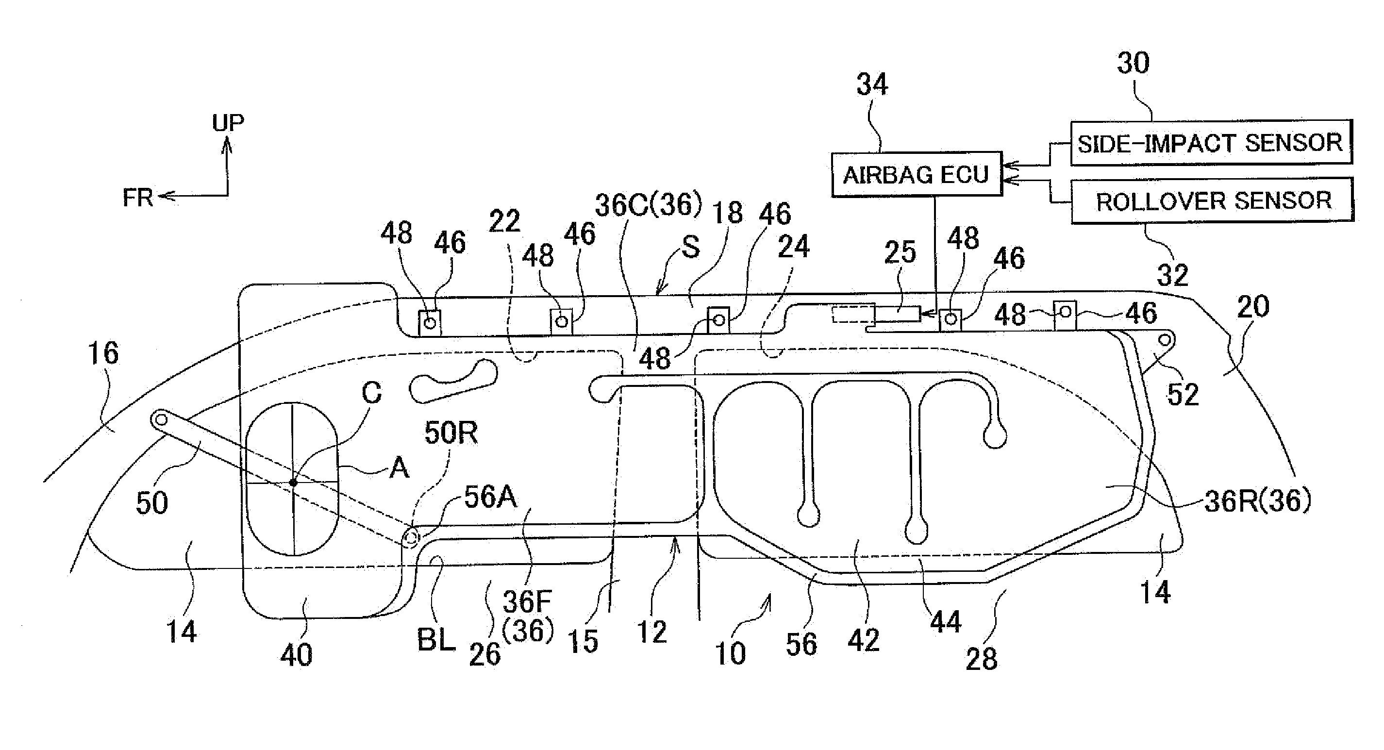
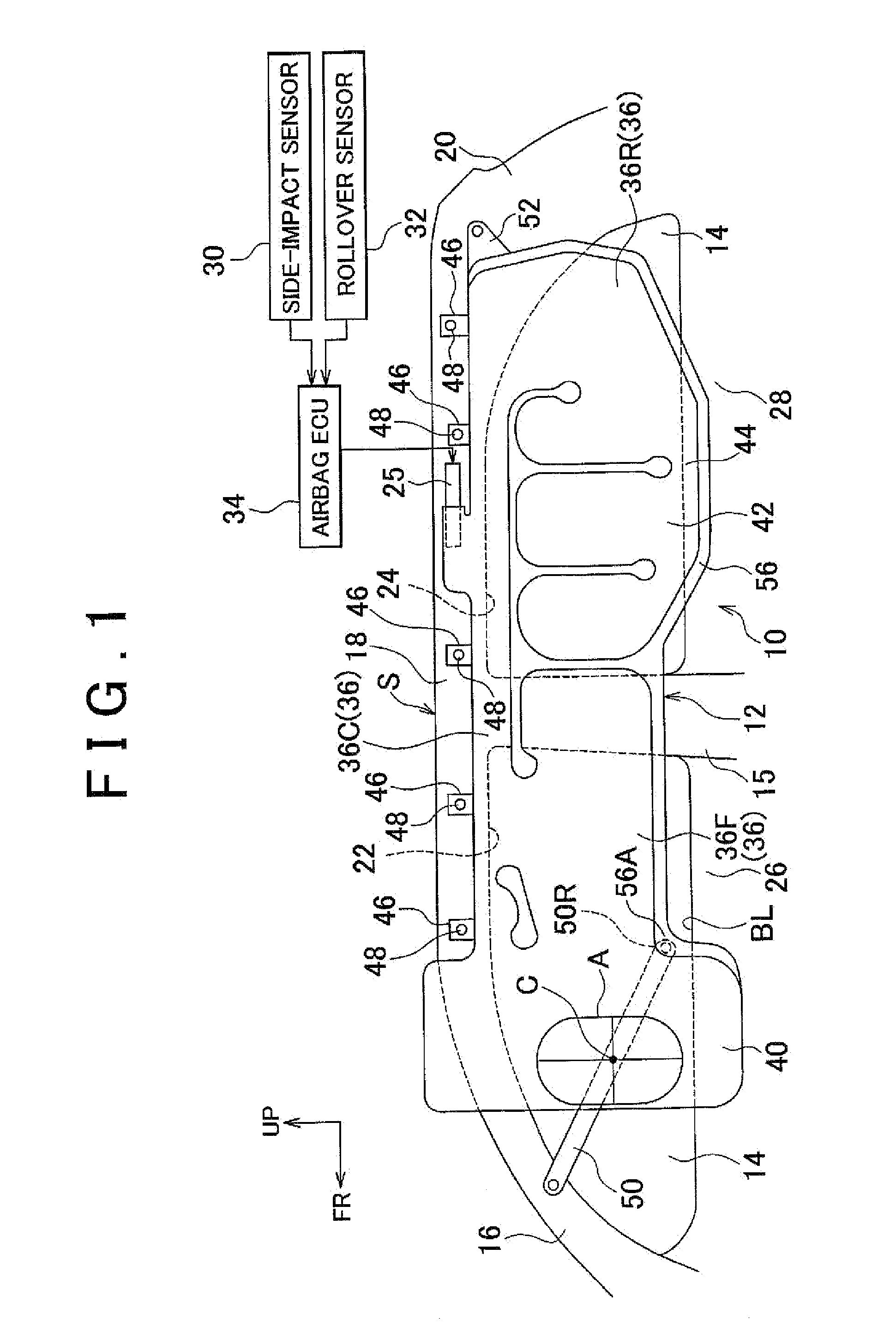
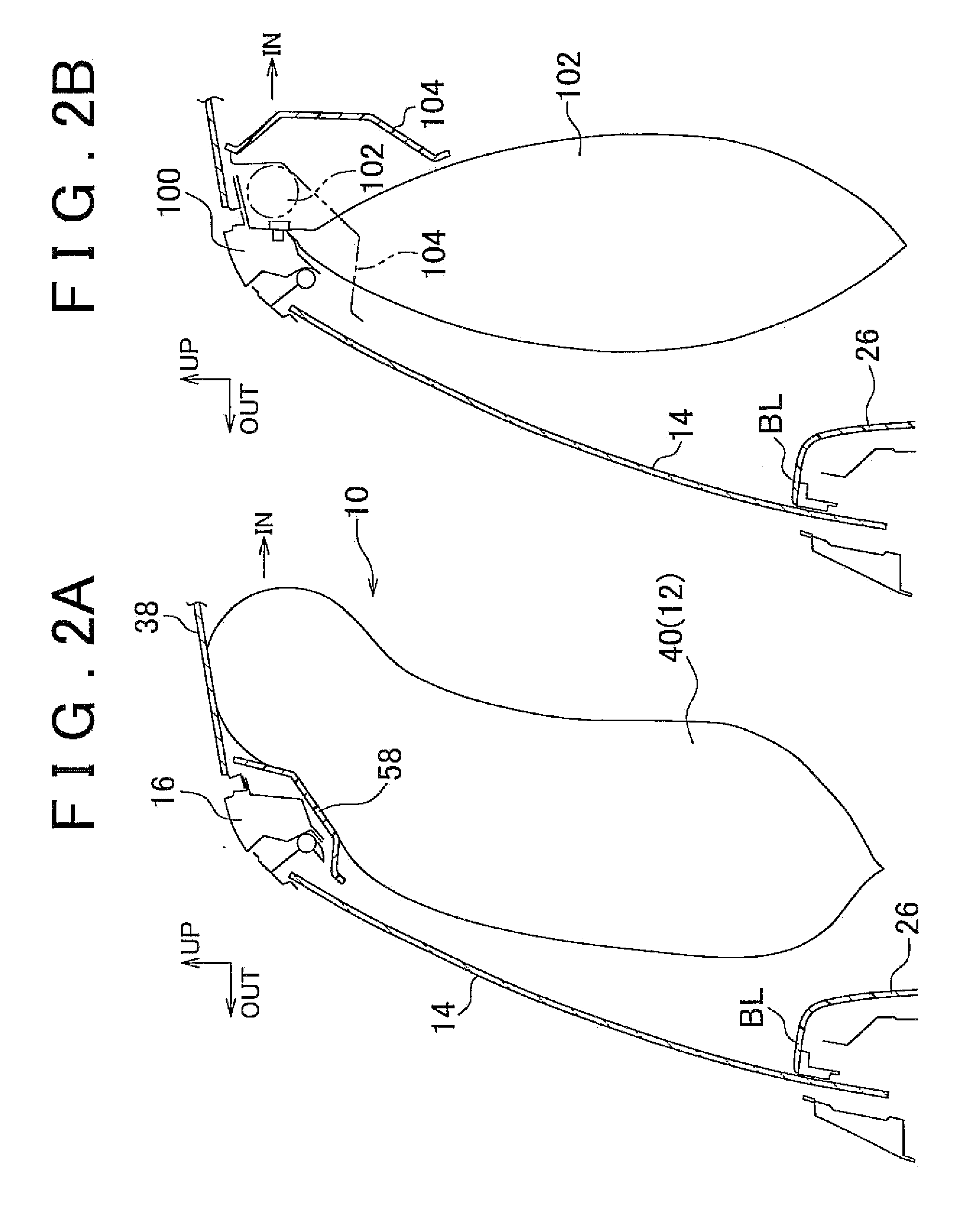
[0028]A curtain airbag system 10 according to one embodiment of the invention will be described with reference to FIG. 1 through FIG. 4. Arrows FR, UP, 1N and OUT denoted in FIG. 1-FIG. 4 as needed represent the front direction (travelling direction), upward direction, inward as viewed in the vehicle width direction, and outward as viewed in the vehicle width direction, respectively, of an automobile S equipped with the curtain airbag system 10. When longitudinal and vertical directions are referred to in the following description, they are supposed to represent the longitudinal direction and vertical direction of the vehicle, respectively, unless otherwise specified.

[0029]FIG. 1 is a side elevation view showing the curtain airbag system 10 when viewed from the vehicle interior or compartment of the automobile S equipped with the system 10. As shown in FIG. 1, the curtain airbag system 10 includes a curtain airbag 12. The curtain airbag 12 is formed so as to be deployed like a curta...


PUM


Abstract

A curtain air bag of a curtain airbag system includes a main chamber stored in a folded condition in a roof side portion that extends rearward from a front pillar, and a front auxiliary chamber formed integrally with the main chamber and stored in a folded condition in the roof side portion together with the main chamber. The main chamber is inflated with gas supplied thereto in the event of a side impact of a vehicle and rollover of the vehicle, to be deployed like a curtain downwardly of the vehicle. The front auxiliary chamber is inflated with gas supplied thereto at least in the event of rollover of the vehicle, to be deployed in front of the main chamber such that an upper portion of the front auxiliary chamber as seen in a side view overlaps the front pillar, and a lower portion thereof overlaps a front side door.

Description

INCORPORATION BY REFERENCE[0001]The disclosure of Japanese Patent Application No. 2011-087665 filed on Apr. 11, 2011 including the specification, drawings and abstract is incorporated herein by reference in its entirety.BACKGROUND OF THE INVENTION[0002]1. Field of the Invention[0003]The invention relates to a curtain airbag system.[0004]2. Description of Related Art[0005]A curtain airbag system is known which includes a main inflatable portion provided at a seating location at which an occupant is seated, and an auxiliary inflatable portion that is constantly in fluid communication with the main inflatable portion via a reduced-diameter portion and is located off the occupant seating location (see, for example, Japanese Patent Application Publication No. 2007-161163 (JP 2007-161163 A)). It is also known to provide a curtain airbag with a second deployment portion that extends below the belt line, at a location other than the occupant seating location (see, for example, Japanese Pate...

Claims


Application Information

Patent Timeline
Patent Type & Authority Applications(United States)
IPC IPC(8): B60R21/20
CPCB60R21/213B60R21/232B60R2021/23386B60R2021/0018B60R21/237
Inventor KATO, HIDEKISHIMIZU, YOSUKE
Owner TOYOTA JIDOSHA KK
Why Eureka
Try Eureka