
Protective case for portable electronic device

Inactive Publication Date: 2012-10-11
SPIGEN KOREA
View PDF12 Cites 68 Cited by
  • Summary
  • Abstract
  • Description
  • Claims
  • Application Information

AI Technical Summary

Benefits of technology

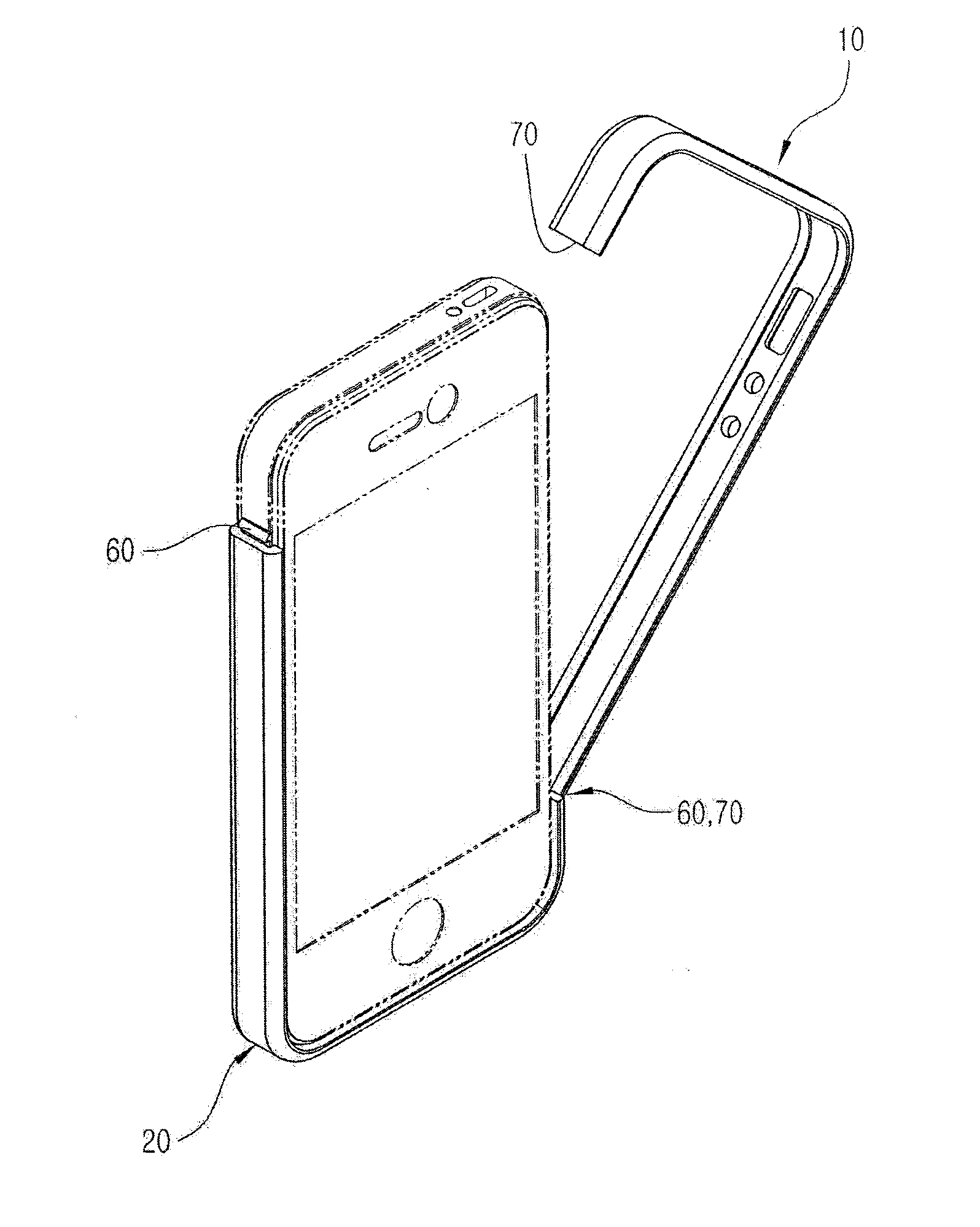
[0013]Aspects of the present invention are to address at least the above-mentioned problems and / or disadvantages and to provide at least the advantages described below. Accordingly, an aspect of the present invention is to provide a protective case for portable electronic devices which is separable into two bodies and wraps the periphery of a portable electronic device, wherein locking parts are disposed at positions not aligned with each other rather than being level with each other, thus not only preventing an external force applied to a portion of the protective case from undesirably easily removing the protective case from the portable electronic device, but also facilitating the operation of coupling the protective case to the electronic device thanks to both using a length difference between the opposite sides of the corresponding body based on the locking parts and using the elasticity of the body.
[0014]Another aspect of the present invention is to provide a protective case for portable electronic devices in which each locking part has an insertion coupling structure using a protrusion and a depression, thus facilitating the operation of coupling the protective case to a portable electronic device or removing it therefrom.
[0015]Another aspect of the present invention is to provide a protective case for portable electronic devices in which a stopper is provided on a locking hook, and a stop protrusion is provided on a corresponding locking catch, so that the locking hook can be smoothly coupled to or removed from the locking catch in a sliding manner, thus further facilitating the coupling or removing operation.
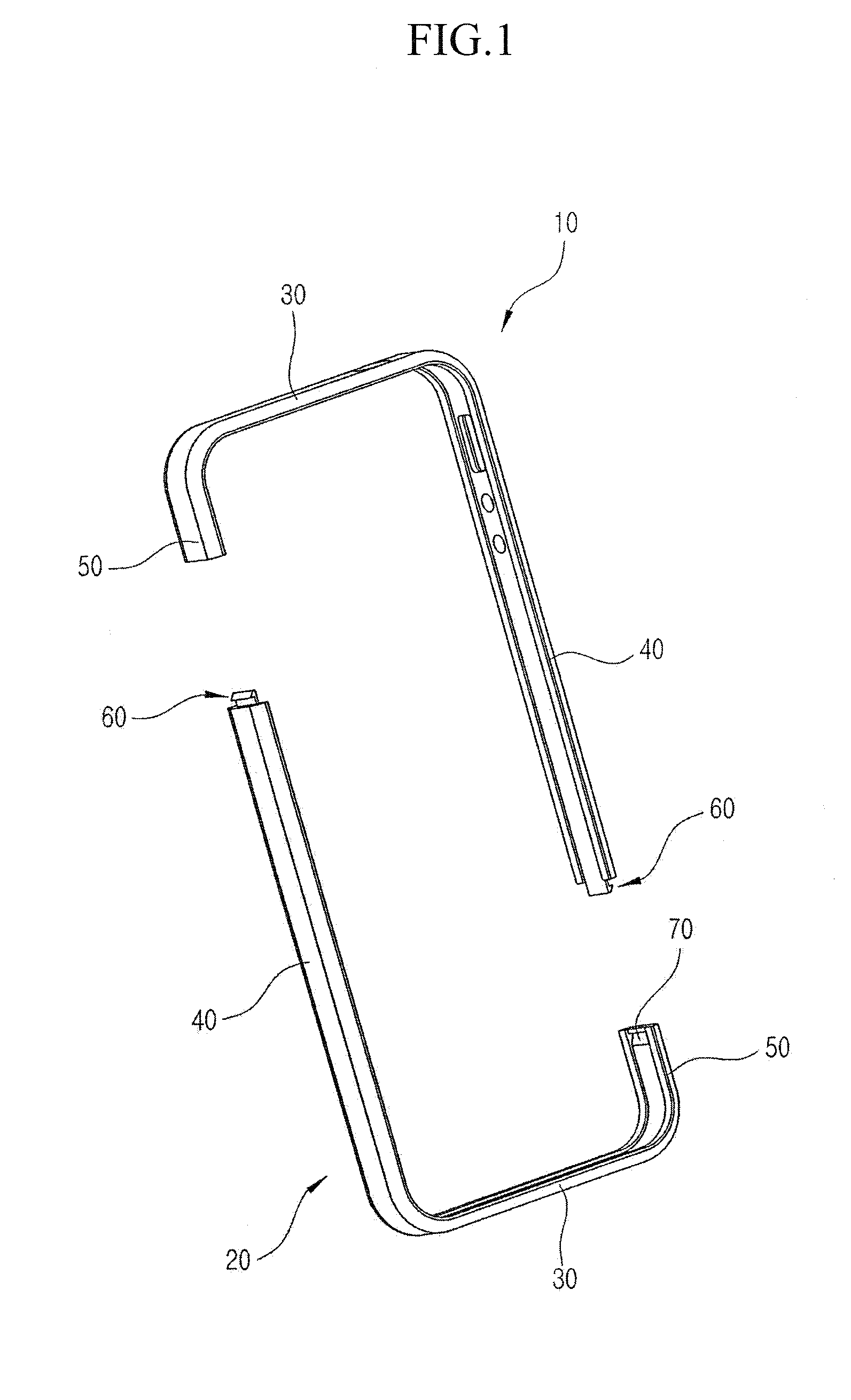
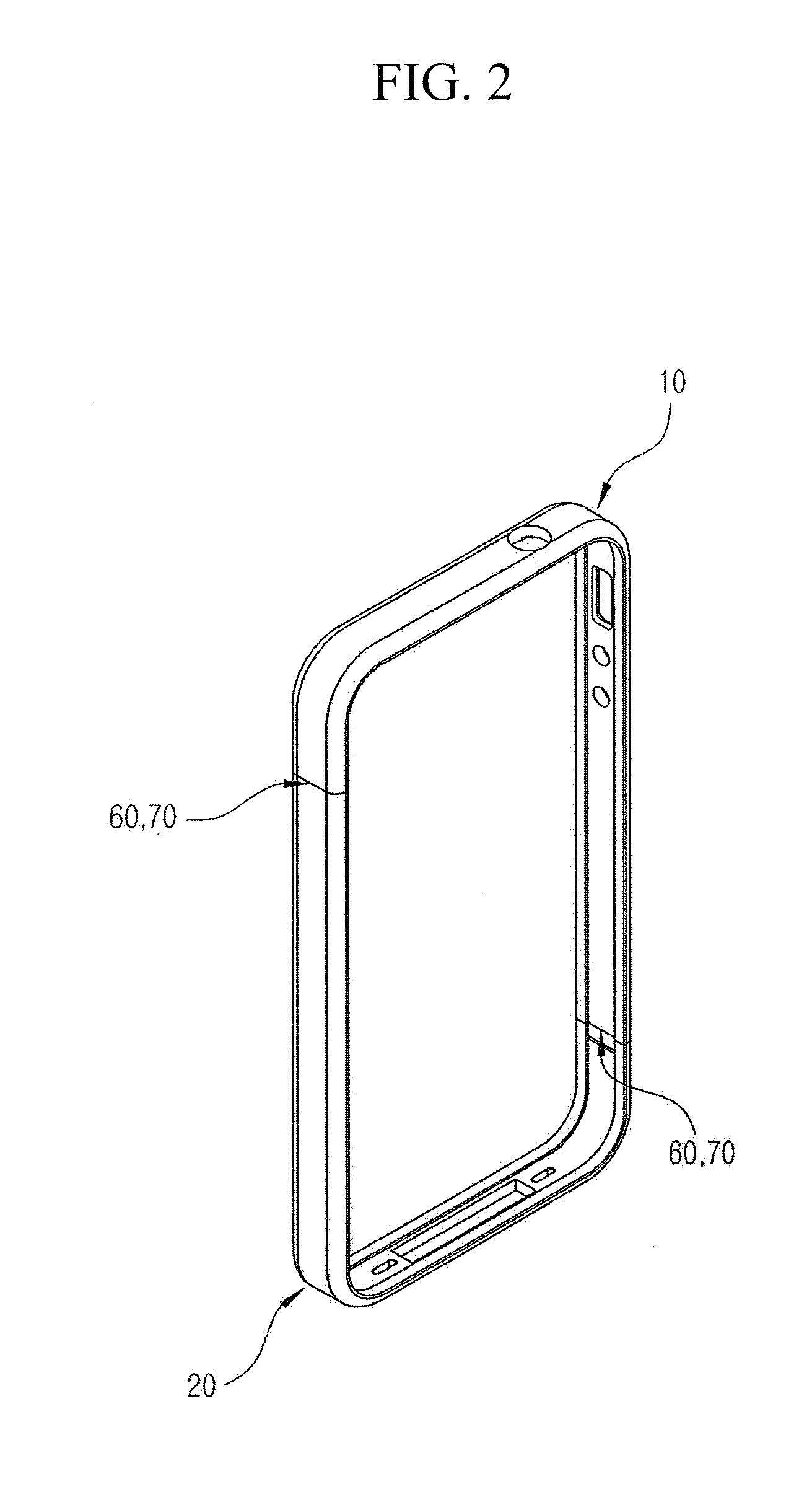
[0016]In accordance with an aspect of the present invention, a protective case for portable electronic devices is provided. The protective case includes first and second bodies covering the side surfaces and portions of perimeters of front and rear surfaces of the portable electronic device in such a way that the first and second bodies are coupled to each other, each of the first and second bodies having a lateral extension part extending in a lateral direction of the portable electronic device, and longitudinal extension parts extending from opposite ends of the lateral extension part in a longitudinal direction, the longitudinal extension parts having a longitudinal short side part and a longitudinal long side part longer than the longitudinal short side part, and locking parts formed on respective junctions between the longitudinal long side part of the first body and the longitudinal short side part of the second body and between the longitudinal long side part of the second body and the longitudinal short side part of the first body, the locking parts removably coupling the first and second bodies to each other.

Problems solved by technology

The display panels of such portable electronic devices are generally vulnerable to impact, so if the devices drop onto the ground, it may cause problems, for example, of damage to the display panels.
The former has an integrated structure, making the use thereof easy, but if the elasticity of the rubber becomes weak, it may stretch and not be able to come into close contact with a portable electronic device, thus reducing the lifetime thereof.
On the other hand, the latter can mitigate the problem of rubber being stretched as time goes by, but because it is typically configured such that locking parts are formed at left and right sides on two bodies of the protective case at the same level, the locking of the locking parts is undesirably easily released by a force that is applied to the protective case in the longitudinal direction.
In addition, coupling two bodies to each other or separating them from each other is far from convenient.

Method used


Image

  • Protective case for portable electronic device
  • Protective case for portable electronic device
  • Protective case for portable electronic device

Examples


Embodiment Construction

[0027]The following description with reference to the accompanying drawings is provided to assist in a comprehensive understanding of exemplary embodiments of the invention as defined by the claims and their equivalents. It includes various specific details to assist in that understanding but these are to be regarded as merely exemplary. Accordingly, those of ordinary skill in the art will recognize that various changes and modifications of the embodiments described herein can be made without departing from the scope and spirit of the invention. In addition, descriptions of well-known functions and constructions may be omitted for clarity and conciseness.

[0028]The terms and words used in the following description and claims are not limited to the bibliographical meanings, but, are merely used by the inventor to enable a clear and consistent understanding of the invention. Accordingly, it should be apparent to those skilled in the art that the following description of exemplary embod...


PUM


Abstract

A protective case for protecting a portable electronic device is provided. The case includes first and second bodies which cover the periphery of the electronic device, and locking parts which separably couple the first and second bodies to each other. Each body includes a lateral extension part which extends in a lateral direction, and longitudinal extension parts which extend in a longitudinal direction. The longitudinal extension parts include a longitudinal short side part which extends from an end of the lateral extension part, and a longitudinal long side part which extends from the other end of the lateral extension part. The locking parts are formed at junctions between the longitudinal long side part of the first body and the longitudinal short side part of the second body and between the longitudinal long side part of the second body and the longitudinal short side part of the first body.

Description

PRIORITY[0001]This application claims the benefit under 35 U.S.C. §119(a) of a Korean patent application filed on Apr. 11, 2010 in the Korean Intellectual Property Office and assigned Serial No. 20-2011-0003035, the entire disclosure of which is hereby incorporated by reference.BACKGROUND OF THE INVENTION[0002]1. Field of the Invention[0003]The present invention relates generally to protective cases for portable electronic devices. More particularly, the present invention relates to a protective case for portable electronic devices which can provide a protective function focused on the periphery of a portable electronic device, facilitate the operation of coupling the protective case to the electronic device or removing it therefrom, and reliably maintain its coupled state.[0004]2. Description of the Related Art[0005]Portable electronic devices refer not only to smartphones, such as I-phones, Android phones, etc., but also to different kinds of electronic devices, for example, elect...

Claims


Application Information

Patent Timeline
IPC IPC(8): H05K7/00
CPCA45C2011/002H04M1/185H04B1/3888
Inventor KIM, DAE-YOUNG
Owner SPIGEN KOREA
Learn More