Vehicle seat

Inactive Publication Date: 2012-10-18
NISSAN MOTOR CO LTD
View PDF20 Cites 113 Cited by
  • Summary
  • Abstract
  • Description
  • Claims
  • Application Information

AI Technical Summary

Benefits of technology

[0007]Therefore, one object presented in the present disclosure is to provide a vehicle seat with which blown

Problems solved by technology

It has been discovered that with the technology disclosed in above mentioned publication, when a passenger sits on a seat cushion, a ventilation portion of a porous sheet and an outer upholstery is crushed by t

Method used


Image

  • Vehicle seat
  • Vehicle seat
  • Vehicle seat

Examples


Embodiment Construction

[0018]Selected embodiments will now be explained with reference to the drawings. It will be apparent to those skilled in the art from this disclosure that the following descriptions of the embodiments are provided for illustration only and not for the purpose of limiting the invention as defined by the appended claims and their equivalents.

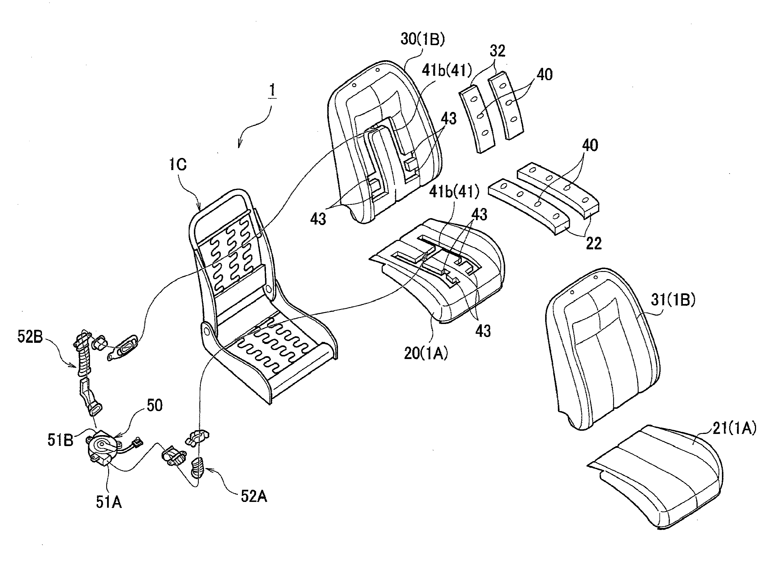
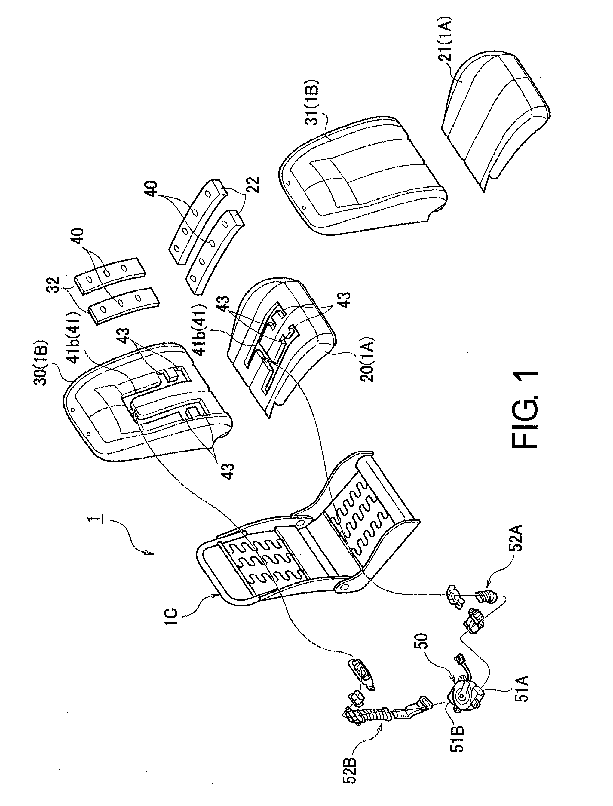
[0019]Referring initially to FIG. 1, a vehicle seat 1 is illustrated in accordance with a first embodiment. The vehicle seat 1 has a seat bottom 1A and a seat back 1B serving as seat bodies. The seat bottom 1A and the seat back 1B are attached to a seat frame 1C.

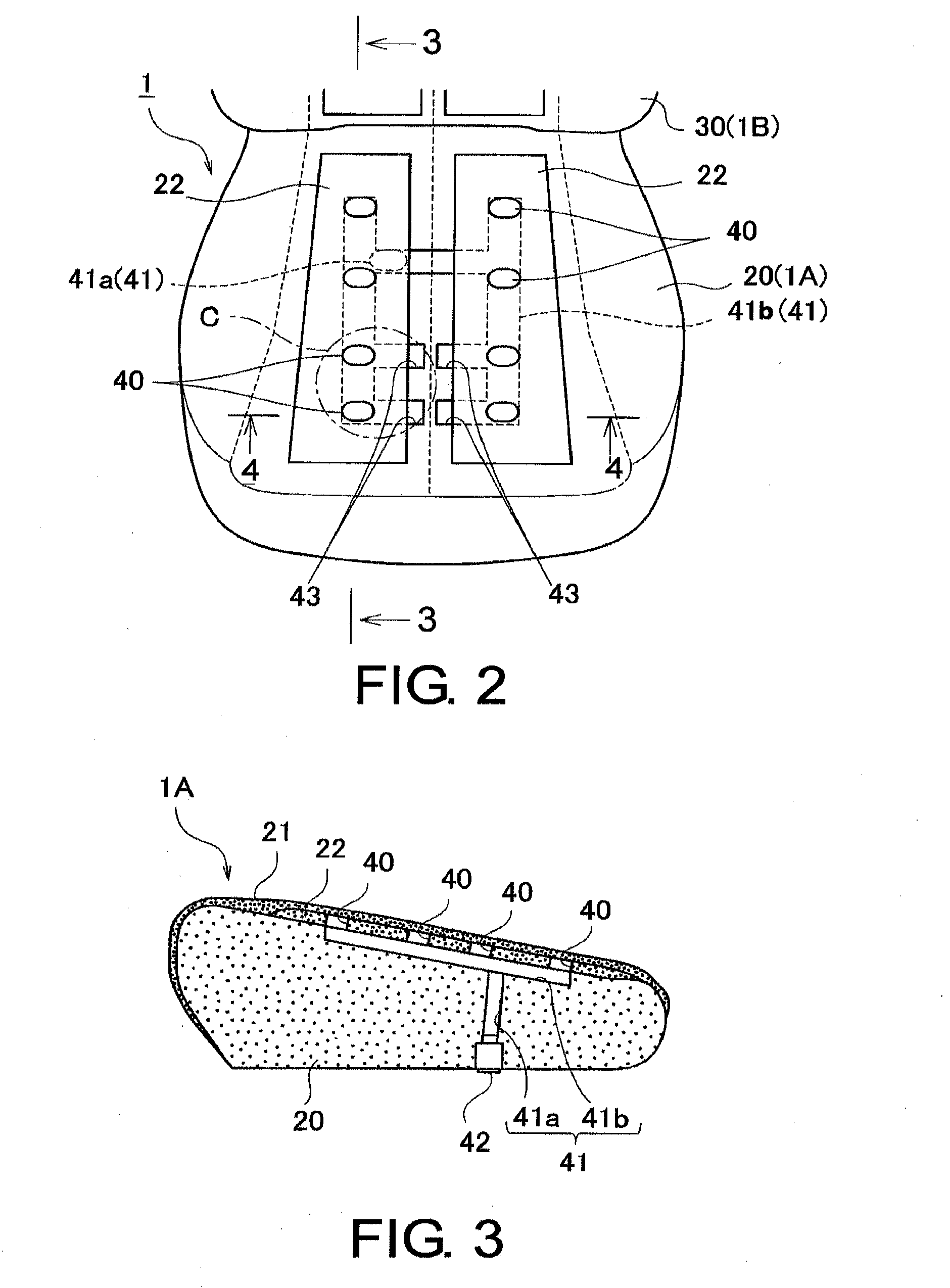
[0020]As shown in FIGS. 2 and 3, the seat bottom 1A includes a seat cushion pad 20, a breathable seat outer cover 21 and an air permeable material layer 22. The seat outer cover 21 covers at least a portion of an outer surface of the seat cushion pad 20. The air permeable material layer 22 is disposed between the seat outer cover 21 and the seat cushion pad 20 at least along portions of th...


PUM


Abstract

A vehicle seat has a cushion pad, a breathable outer cover and an air permeable material layer. The cushion pad includes an air passage extending from an air introducing port disposed at the non-passenger facing surface to a branch passage formed along the passenger facing surface. The branch passage has at least one bypass air passage that extends in a vehicle-widthwise direction of the cushion pad. The breathable outer cover is disposed over the passenger facing surface of the cushion pad. The air permeable material layer is disposed between the cushion pad and the breathable outer cover. The air permeable material layer includes a plurality of vent outlets passing through in a thickness direction of the air permeable material layer. The vent outlets are arranged in at least one column that extends in a direction perpendicular to the vehicle-widthwise direction.

Description

CROSS-REFERENCE TO RELATED APPLICATIONS[0001]This application claims priority to Japanese Patent Application No. 2011-088719, filed on Apr. 13, 2011. The entire disclosure of Japanese Patent Application No. 2011-088719 is hereby incorporated herein by reference.BACKGROUND[0002]1. Field of the Invention[0003]The present invention generally relates to a seat for a vehicle. More specifically, the present invention relates to a vehicle seat having an air passage for introducing air to a cushion pad of the vehicle seat.[0004]2. Background Information[0005]Japanese Laid-Open Patent Publication No. H09-505499 discloses a seat cushion structure that has a cushion pad with a flow passage for introducing conditioned air to the cushion pad. In this publication, air is blown into the cushion pad through the flow passage. The air exits from the cushion pad by an outlet on an outer surface side of the cushion pad. The air exits from the cushion pad and passes through a porous sheet that is coveri...

Claims


Application Information

Patent Timeline
IPC IPC(8): B60N2/56B60N2/90
CPCB60N2/5657B60N2/5642
Inventor YOSHIZAWA, NORIMICHIEGAMI, MASAHIROTAKAHASHI, MIHARU
Owner NISSAN MOTOR CO LTD
Why Eureka
Try Eureka