Image display device, vision aid and stereo image display system using the same

Inactive Publication Date: 2012-10-18
SHARP KK
View PDF2 Cites 13 Cited by
  • Summary
  • Abstract
  • Description
  • Claims
  • Application Information

AI Technical Summary

Benefits of technology

[0006]An object of the present invention is to provide an image display device where the display mode of the display unit can be appropriately switched betwee

Problems solved by technology

However, in the conventional arrangement above, the screen may not be switched to the planar image mode when the user takes the

Method used


Image

  • Image display device, vision aid and stereo image display system using the same
  • Image display device, vision aid and stereo image display system using the same
  • Image display device, vision aid and stereo image display system using the same

Examples


embodiments

[0036]Now, embodiments of the present invention will be described in more detail with reference to the drawings. The identical and corresponding portions in the drawings are labeled with the same numerals and their description will not be repeated.

First Embodiment

[0037]Configuration of Stereo Image Display System

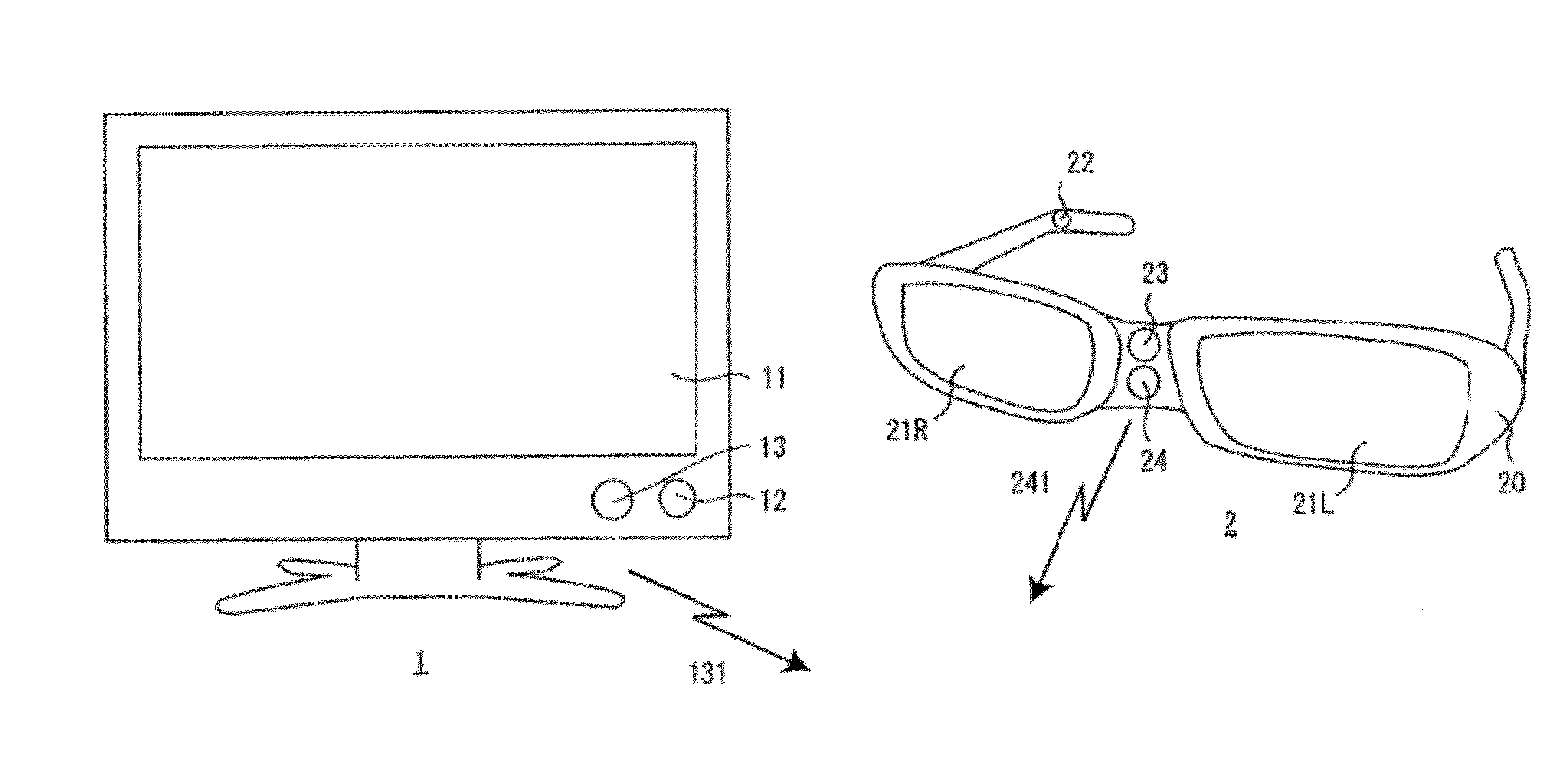
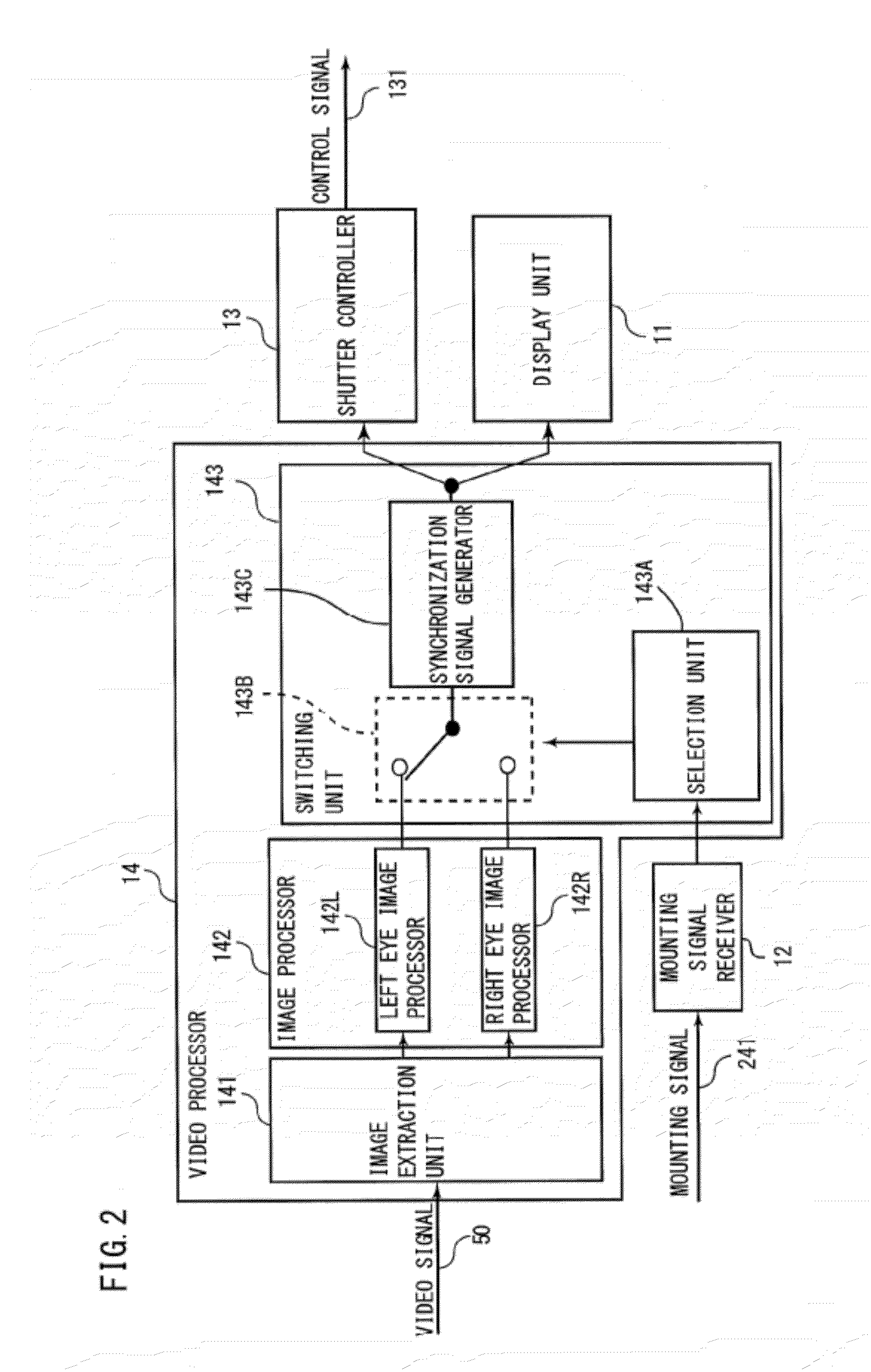
[0038]First, referring to FIG. 1, the configuration of a stereo image display system will be described. The stereo image display system shown in FIG. 1 includes an image display device 1 and a vision aid 2.

[0039]In the present implementation, the image display device 1 is a liquid crystal display; however, any light-emitting display or non-light-emitting display may be used. Examples of light-emitting displays include, but are not limited to, a cathode-ray tube, a plasma display, an organic electroluminescent device, an inorganic electroluminescent device, and a field-emission display. Examples of non-light-emitting displays include, but are not limited to, a liquid crystal ...

first embodiment

Variations of First Embodiment

[0099]In the first embodiment, the mounting detector 22 implemented as a push switch that can be pressed in when it comes in contact with the head of the user has been described; however, the following variations are also possible. That is, the mounting detector 22 may be of any configuration that allows it to detect that it is in contact with, or close to, a portion of the user's body. For example, the mounting detector 22 may be implemented as a touch sensor, a pressure sensor, a slide switch, a human-sensitive sensor or the like.

[0100]Touch sensors include, for example, capacitive or resistive touch sensors. Alternatively, a photosensitive touch sensor may be used.

[0101]A slide switch may be employed, for example, in a goggle-type vision aid 2 that can be mounted on the head of the user by means of an elasticized band. That is, the band is stretched when the user wears the vision aid 2 on his head. As such, a slide switch may be provided on the band ...

second embodiment

Variation of Second Embodiment

[0119]The above description of the second embodiment has illustrated an implementation where the display mode is switched to the stereo image display mode if Yes at step S1105. However, in a variation thereof, instead of step S1105, it may be determined whether the number of vision aids 2 considered to be mounted on the head of a user is at least one and, if Yes, the process proceeds to step S1106 or, if No, the process proceeds to step S1112.

[0120]Alternatively, one of the vision aids 2 may be designated as a representative vision aid (hereinafter referred to as “parent”), and the display mode of the display unit 11 may be switched to the stereo image display mode if it is determined that the parent is mounted on the head of a user and may be switched to the planar image display mode if it is determined that the parent is not mounted on the head of a user.

[0121]Further, although the second embodiment has illustrated an implementation where a mounting s...


PUM


Abstract

An image display device where the display mode can be appropriately switched depending on whether a vision aid is in contact with or close to a portion of a user's body is provided. An image display device (1) includes a display unit (11) that performs display in the stereo image display mode for displaying, separately in time or space, a left eye image to be viewed through a left eye portion (21L) of a vision aid (2) and a right eye image to be viewed through a right eye portion (21R) of the vision aid (2), or a planar image display mode for displaying one of the left eye image and the right eye image.
The image display device (1) receives, from the vision aid (2), a mounting signal (241) that indicates that the vision aid is in contact with or close to a portion of the user's body and switches the display mode of the display unit (11) between the stereo image display mode and the planar image display mode based on the reception condition of the signal.

Description

TECHNICAL FIELD[0001]The present invention relates to an image display device, a vision aid and a stereo image display system using the same, and more particularly, an image display device, a vision aid and a stereo image display system using the same employing glasses methods, in which a user wears special glasses to view stereo images.BACKGROUND ART[0002]In recent years, increasingly active research and development have been conducted toward the end of putting into practical use a stereo image display system that allows the viewer to view stereoscopic images.[0003]Conventional stereo image display systems are generally categorized into: (1) stereo image display systems using so-called glasses methods, in which an image display device displays left and right eye images with a parallax and the viewer wears special glasses (i.e. a vision aid) that allow him to view only left eye images with his left eye and only right eye images with his right eye; and (2) so-called glasses-free ster...

Claims


Application Information

Patent Timeline
IPC IPC(8): G06T15/00
CPCG02B27/2264G03B35/16H04N2213/008H04N13/0438H04N13/0454G09G3/003G02B30/24H04N13/341H04N13/359
Inventor TADAO, MORISHITA
Owner SHARP KK
Why Eureka
Try Eureka