Robotic work object cell calibration method
a robot and work object technology, applied in the direction of electric programme control, program control, instruments, etc., can solve the problems of specialized users, expensive equipment in the prior art system, and the time-consuming and labor-intensive nature of the process
- Summary
- Abstract
- Description
- Claims
- Application Information
AI Technical Summary
Benefits of technology
Problems solved by technology
Method used
Image
Examples
Embodiment Construction
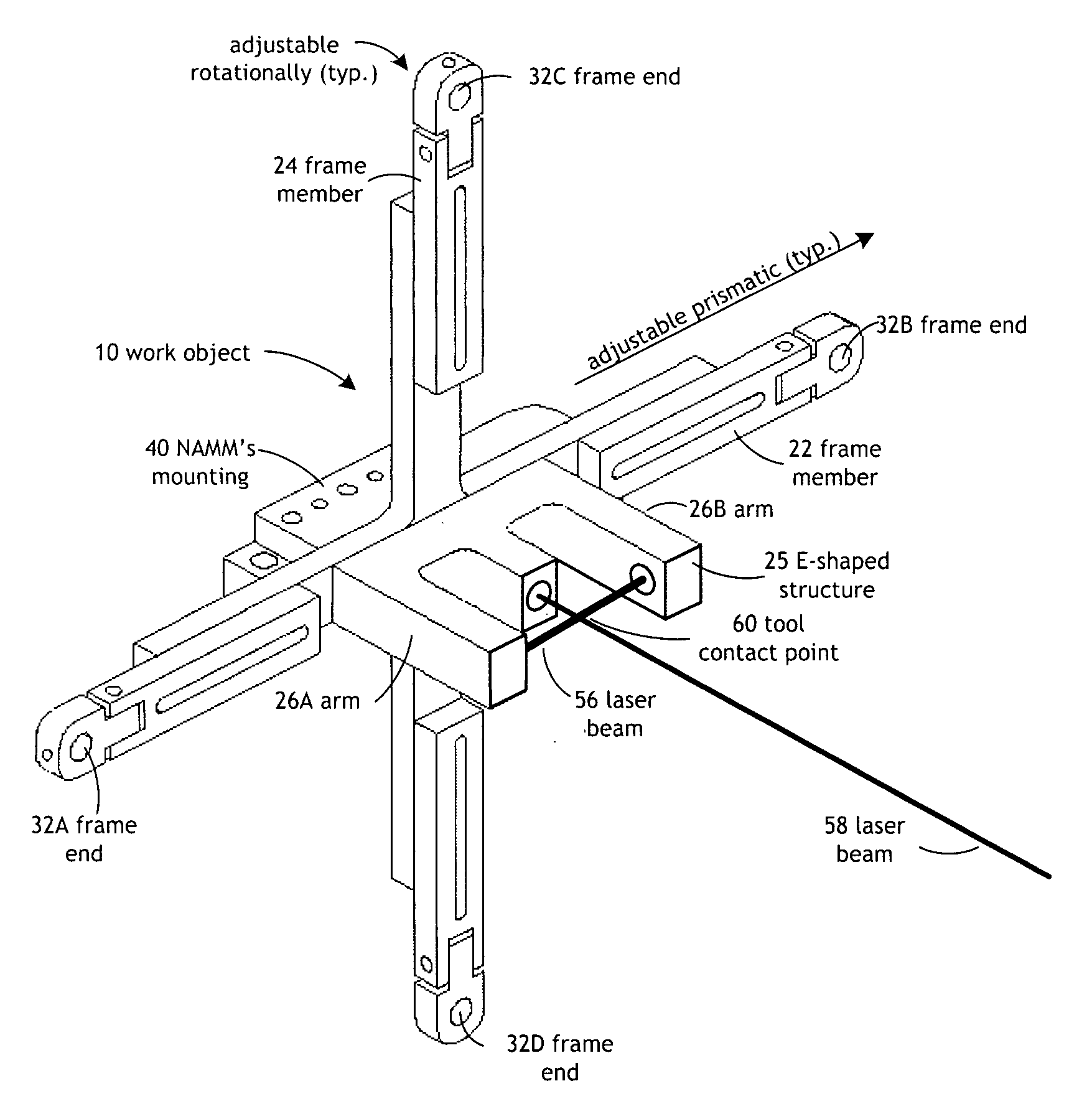
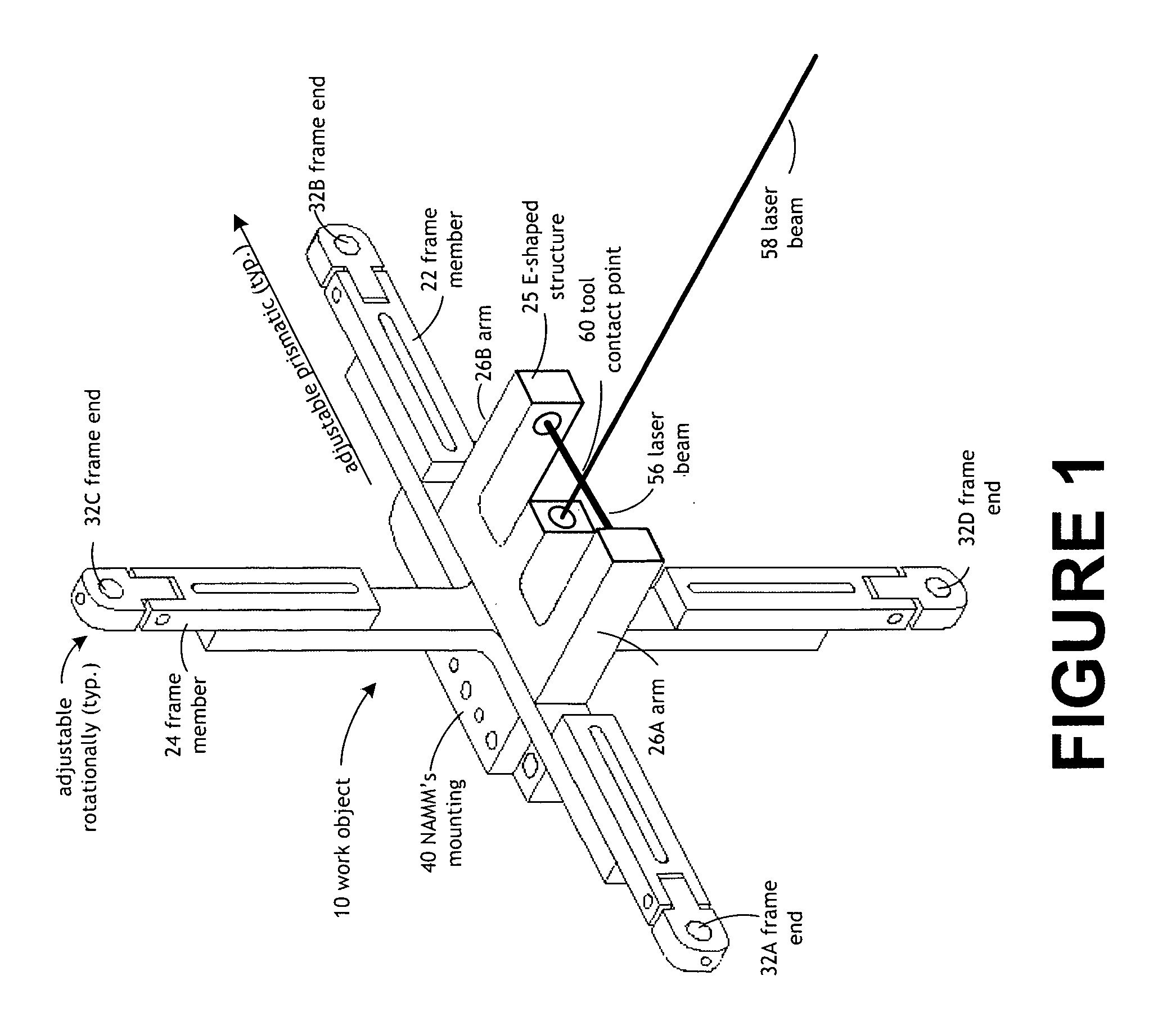
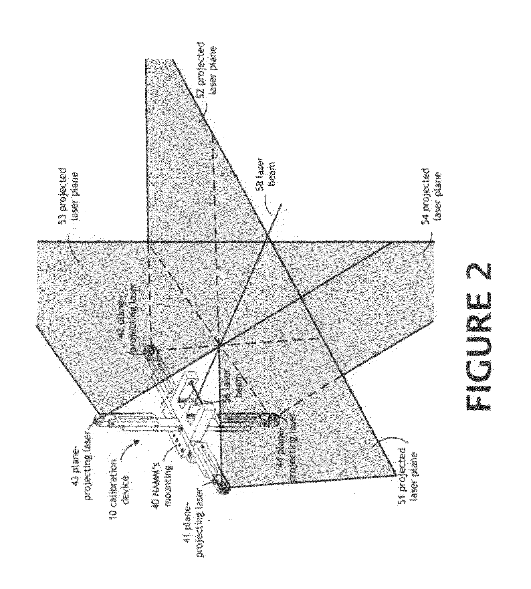
[0033]Referring now to the drawings, FIGS. 1 and 2 disclose a first preferred embodiment of a work object or emitter [10] for use in the robotic work object calibration method of the present invention. The work object [10] is used to calibrate the work path of a robot tool based on a tool contact point (point in space) [60]. The known point in space [60] is defined in three dimensions (X, Y, and Z) and relative to their rotational axes Rx (pitch), Ry (yaw), and Rz (roll).
[0034]The work object [10] includes a horizontal frame member [22] that includes a pair of opposing frame ends [32A and 32B], and a vertical frame member [24] that includes a pair of opposing frame ends [32C and 32D]. A plane-projecting laser [41, 42, 43, and 44] is preferably disposed at each frame end [32A, 32B, 32C, and 32D], respectively, and a projected laser plane [51, 52, 53, and 54] is emitted from each of the plane-projecting lasers [41, 42, 43, and 44], respectively.
[0035]Extending along the horizontal fra...
PUM
 Abstract
Description
Claims
Application Information
 - R&D
- Intellectual Property
- Life Sciences
- Materials
- Tech Scout
- Unparalleled Data Quality
- Higher Quality Content
- 60% Fewer Hallucinations
Browse by: Latest US Patents, China's latest patents, Technical Efficacy Thesaurus, Application Domain, Technology Topic, Popular Technical Reports.
© 2025 PatSnap. All rights reserved.Legal|Privacy policy|Modern Slavery Act Transparency Statement|Sitemap|About US| Contact US: help@patsnap.com


