Robotic work object cell calibration method

a robot and work object technology, applied in the direction of electric programme control, program control, instruments, etc., can solve the problems of specialized users, expensive equipment in the prior art system, and the time-consuming and labor-intensive nature of the process

Active Publication Date: 2015-06-23
TROMPETER MATTHEW E
View PDF25 Cites 4 Cited by
  • Summary
  • Abstract
  • Description
  • Claims
  • Application Information

AI Technical Summary

Benefits of technology

[0019]A fourth preferred embodiment of the work object of the present invention comprises only one plane-projecting laser attached to the middle of the work object. The laser head is capable of 360 degrees of rotation, enabling the robot tool to align first on the x-axis, then on the y-axis after the laser head has been rotated.
[0021]For a complete understanding of the robotic work object cell calibration method of the present invention, reference is made to the following summary of the invention detailed description and accompanying drawings in which the presently preferred embodiments of the invention are shown by way of example. As the invention may be embodied in many forms without departing from spirit of essential characteristics thereof, it is expressly understood that the drawings are for purposes of illustration and description only, and are not intended as a definition of the limits of the invention.

Problems solved by technology

Prior art systems involve expensive equipment and specialized users and take longer.

Method used


Image

  • Robotic work object cell calibration method
  • Robotic work object cell calibration method
  • Robotic work object cell calibration method

Examples


Embodiment Construction

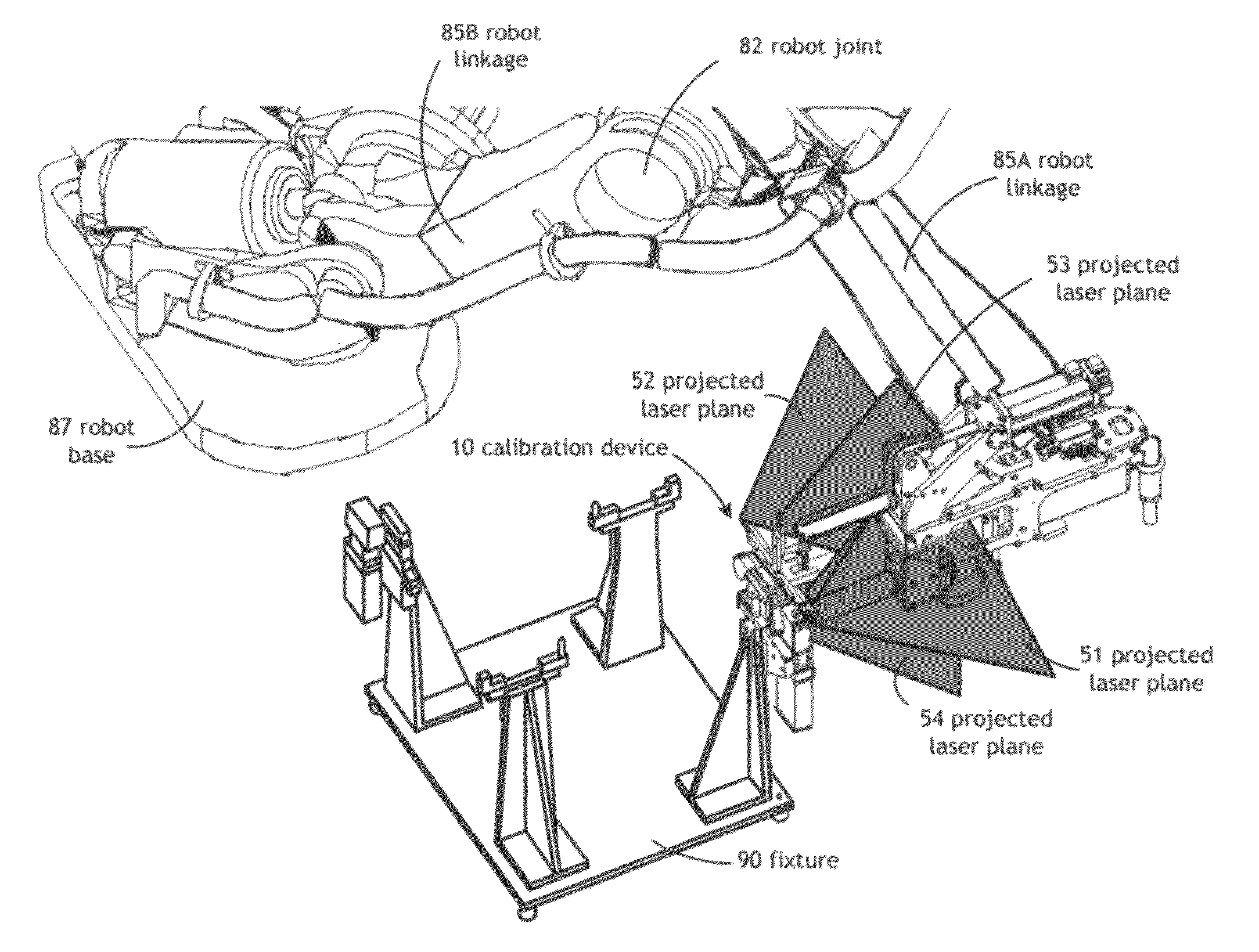
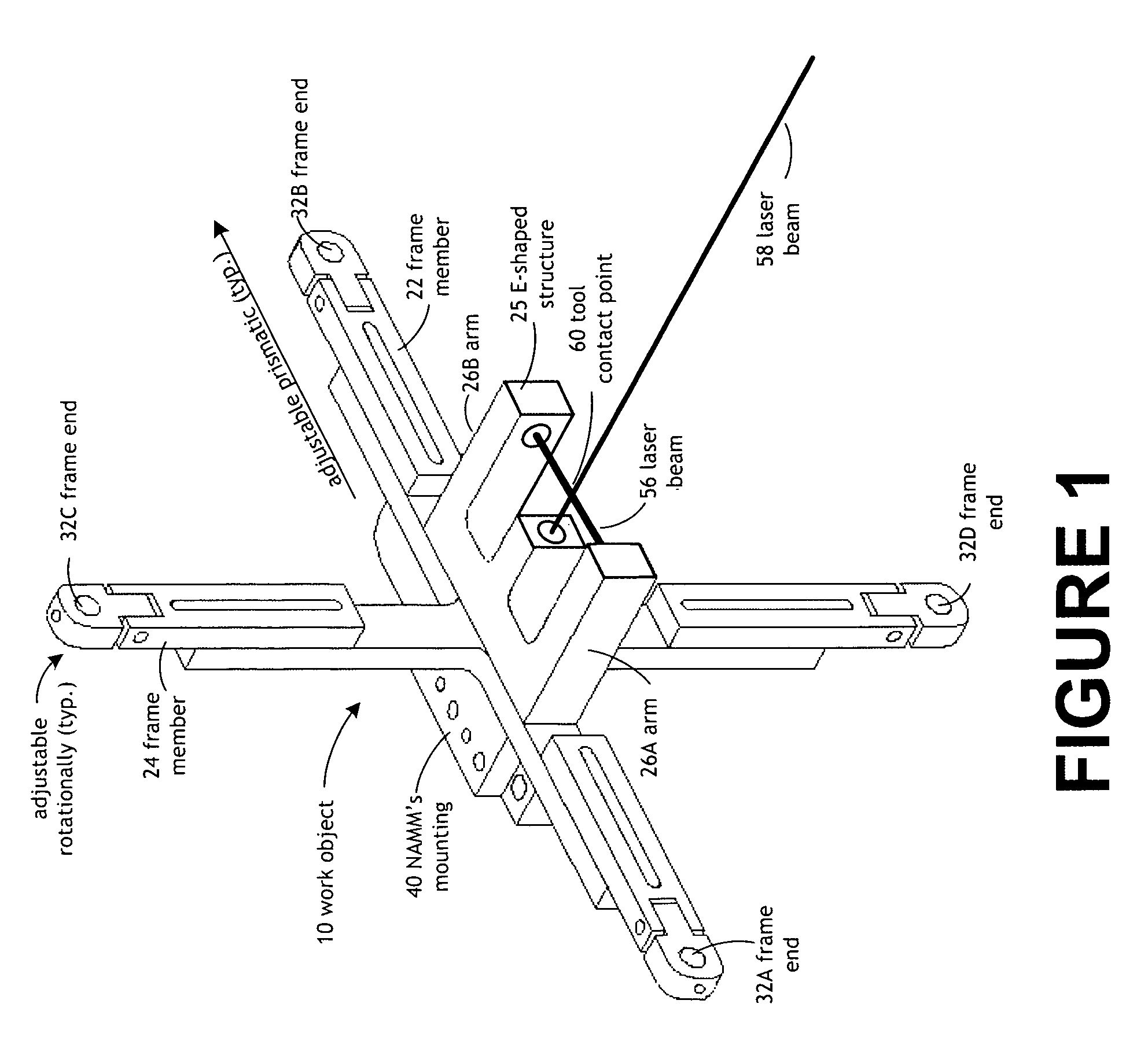
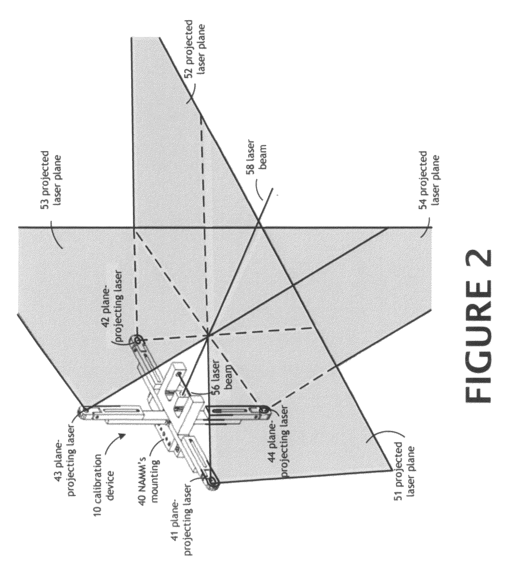
[0033]Referring now to the drawings, FIGS. 1 and 2 disclose a first preferred embodiment of a work object or emitter [10] for use in the robotic work object calibration method of the present invention. The work object [10] is used to calibrate the work path of a robot tool based on a tool contact point (point in space) [60]. The known point in space [60] is defined in three dimensions (X, Y, and Z) and relative to their rotational axes Rx (pitch), Ry (yaw), and Rz (roll).

[0034]The work object [10] includes a horizontal frame member [22] that includes a pair of opposing frame ends [32A and 32B], and a vertical frame member [24] that includes a pair of opposing frame ends [32C and 32D]. A plane-projecting laser [41, 42, 43, and 44] is preferably disposed at each frame end [32A, 32B, 32C, and 32D], respectively, and a projected laser plane [51, 52, 53, and 54] is emitted from each of the plane-projecting lasers [41, 42, 43, and 44], respectively.

[0035]Extending along the horizontal fra...


PUM


Abstract

The robotic work object cell calibration method includes a work object or emitter. Initially, placing the work object is placed in a selected position on a fixture or work piece on the shop floor. The work object emits a pair of beam-projecting lasers which intersect at a tool contact point and act as a crosshair. The robot tool is manipulated into the tool contact point. The work object emits four plane-projecting lasers which are used to adjust the roll, yaw, and pitch of the robot tool relative to the tool contact point. The robotic work object cell calibration method of the present invention increases the accuracy of the off-line programming and decreases robot teaching time.

Description

[0001]This application is related to and claims priority to U.S. Provisional Application No. 61 / 465,080, entitled “Robotic Work Object Cell Calibration System and Method,” filed on Mar. 14, 2011; to U.S. Provisional Application No. 61 / 518,912, entitled “Robotic Work Object Cell Calibration System and Method,” filed on May 13, 2011; and to U.S. patent application Ser. No. 13 / 385,091 “Robotic Work Object Cell Calibration System,” filed on Feb. 1, 2012. The disclosures of these Applications are hereby incorporated by reference into this specification in their entireties.FIELD OF USE[0002]The present invention relates to a calibration device and method for an industrial robot and, more particularly, to a calibration method for the industrial robot provided with an imaging device of a visual sensor for detecting a working tool and a working position.BACKGROUND OF THE INVENTION[0003]The sales of industrial robots that has been driven by the automotive industry, is now moving into tasks as...

Claims


Application Information

Patent Timeline
Patent Type & Authority Patents(United States)
IPC IPC(8): B25J9/16
CPCB25J9/1692G05B2219/39033
Inventor TROMPETER, MATTHEW E.
Owner TROMPETER MATTHEW E
Why Eureka
Try Eureka