Torsional vibration damper

a damper and torsional technology, applied in the direction of fluid gearings, couplings, fluid gearings, etc., can solve the problem of rather high manufacturing cost of the damper device described in wo 2016/208765 a1 and other problems, to achieve the effect of effective damped, increased relative rotation between the input element and the output element, and increased stroke of the elastic member

Active Publication Date: 2020-08-20
AISIN FUKUI CORP +2
View PDF0 Cites 0 Cited by
  • Summary
  • Abstract
  • Description
  • Claims
  • Application Information

AI Technical Summary

Benefits of technology

[0005]The present disclosure has been conceived noting the above-described technical problems, and it is therefore an object of the present disclosure to enhance a vibration damping performance of a torsional vibration damper by increasing an oscillation range of a planetary element in a direction that the planetary element is moved by an engine torque.
[0009]According to the embodiment of the present disclosure, torque of the engine is applied to the input element of the torsional vibration damper. The elastic member is interposed between the input element and the output element while being held in the spring holder formed by the apertures of the input element and the output element. When the relative rotation between the input element and the output element is not caused and the elastic member is not compressed, each of the planetary element is individually situated at an initial position. As described, the first movable range extending from the initial position in the drive direction is wider than the second movable range extending from the initial position in the counter direction. According to the embodiment of the present disclosure, therefore, a degree of relative rotation between the input element and the output element may be increased and a stroke of the elastic member can be increased. For these reasons, the planetary elements are allowed to further rotate in the drive direction compared to the conventional art. By thus increasing the movable range of the planetary elements in the drive direction, a spring constant of the elastic member can be reduced to be further compressed compared to the conventional art. Consequently, a resonance point of the torsional vibration damper can be shifted to the low speed side. According to the embodiment of the present disclosure, therefore, torsional vibrations resulting from pulsation of an input torque to the torsional vibration damper can be damped effectively in a low speed range of the engine without increasing a size of the torsional vibration damper.

Problems solved by technology

Thus, large number of parts are required to form the damper device described in WO 2016 / 208765 A1, and hence a manufacturing cost of the damper device described in WO 2016 / 208765 A1 may be rather high.

Method used


Image

  • Torsional vibration damper
  • Torsional vibration damper
  • Torsional vibration damper

Examples


first example

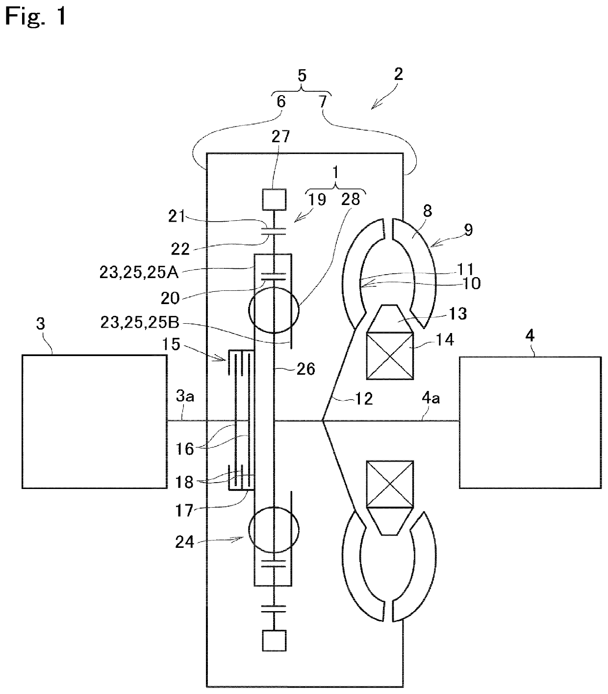
[0017]Examples of the present disclosure will now be explained with reference to the accompanying drawings. Turning now to FIG. 1, there is shown the first example of the torsional vibration damper 1 arranged in a torque converter 2. As illustrated in FIG. 1, in the torque converter 2, the torsional vibration damper 1 is disposed on a torque transmission path between a prime mover 3 and a drive object 4. For example, an internal combustion engine such as a gasoline engine and a diesel engine may be adopted as the prime mover (as will be called the “engine” hereinafter) 3, and an output torque of the engine 3 pulsates inevitably. A torque of the engine 3 is increased with an increase in a speed of the engine 3, but reduced after the speed of the engine 3 is increased higher than a speed at which the torque of the engine 3 is increased to a maximum torque. The pulsation of the torque of the engine 3 is reduced with an increase in the speed of the engine 3. For example, the drive objec...

second example

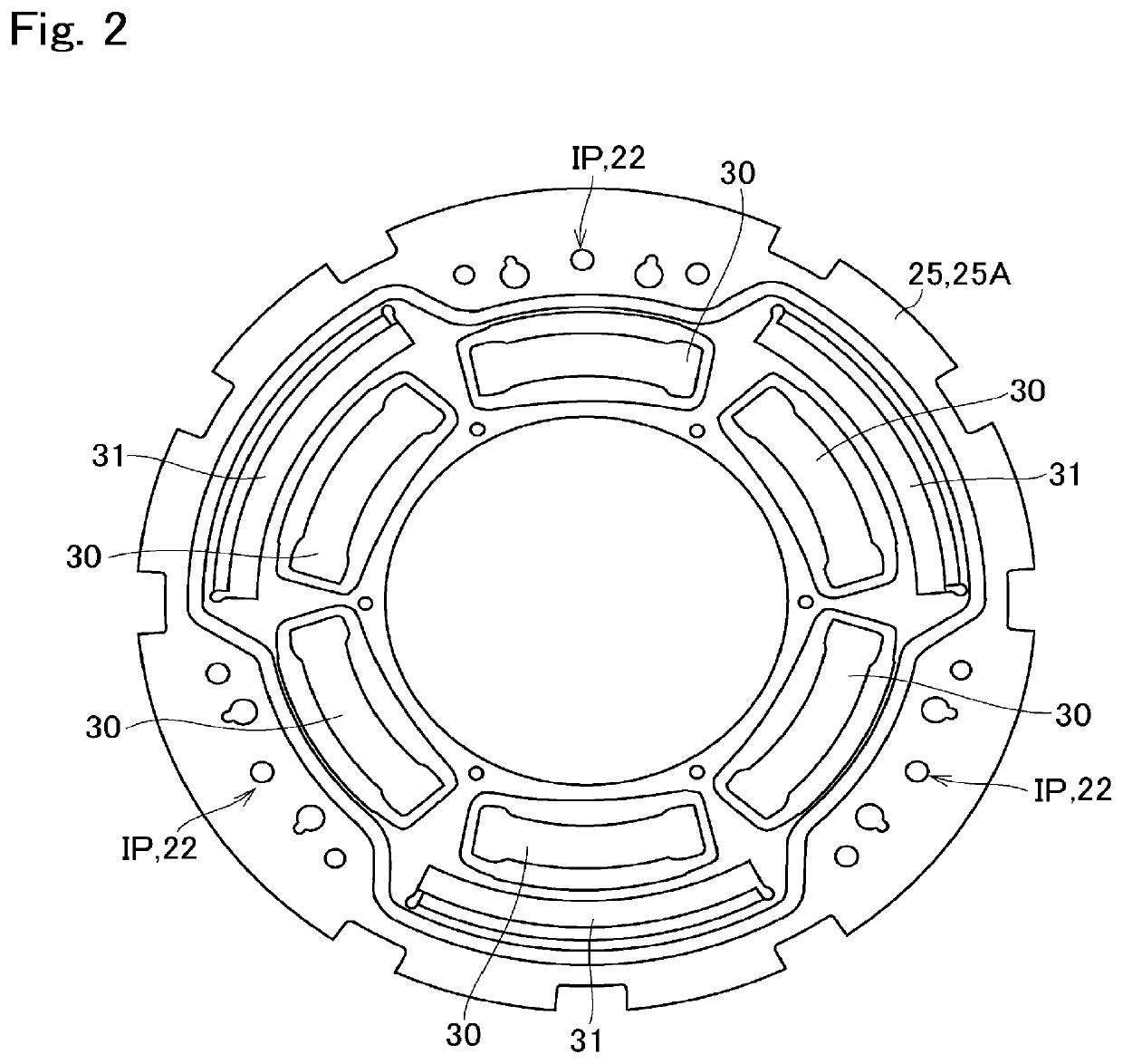
[0037]Turning to FIG. 5, there is shown a second example of the first drive plate 25A. As illustrated in FIG. 5, in the first drive plate 25A according to the second example, each of the first apertures 30 is individually displaced in the drive direction by a predetermined degree so that the initial position IP of each of the pinion gears 22 is situated radially outer side of an end section of the first aperture 30 in the counter direction. The second drive plate 25B has a same configuration as the first drive plate 25A, and the first drive plate 25A and the second drive plate 25B are joined to each other through the connection means 35 in such a manner that e.g., top surfaces of the first drive plate 25A and the second drive plate 25B are opposed to each other. The remaining structure of the drive plate 25 according to the second example is identical to that of the drive plate 25A according to the first example.

[0038]FIG. 5 is a partial front view showing a structure of the torsion...


PUM


Abstract

A torsional vibration damper that damps torsional vibration effectively in a low-speed range. In the torsional vibration damper, a spring holder is formed by apertures of an input element and an output element, and an elastic member is held in the spring holder. A first moveable range of a planetary element extending from an initial position in a drive direction is wider than a second movable range of the planetary element extending from the initial position in a counter direction.

Description

CROSS REFERENCE TO RELATED APPLICATION[0001]The present disclosure claims the benefit of Japanese Patent Application No. 2019-024558 filed on Feb. 14, 2019 with the Japanese Patent Office, the disclosure of which is incorporated herein by reference in its entirety.BACKGROUNDField of the Disclosure[0002]Embodiments of the present disclosure relate to the art of a torsional vibration damper that suppresses torsional vibrations resulting from torque pulse.Discussion of the Related Art[0003]WO 2016 / 208765 A1 describes an example of a damper device having a planetary gear unit for suppressing torsional vibrations resulting from torque pulse. In the damper device taught by WO 2016 / 208765 A1, the planetary gear unit is arranged in a torque converter having a lock-up clutch around a spring damper. In the planetary gear unit, a carrier is connected to the lockup clutch and a drive member of the spring damper so that a torque of an engine is applied to the carrier through the lock-up clutch, ...

Claims


Application Information

Patent Timeline
Patent Type & Authority Applications(United States)
IPC IPC(8): F16F15/134F16D3/12F16F15/14
CPCF16H2045/0268F16H2045/0231F16D3/12F16F15/13469F16H45/02F16F15/1478F16F15/123F16H57/0006F16H57/08F16H1/32F16H2045/0284Y02T10/62
Inventor IWAGAKI, TOMONISHIDA, HIDEYUKIISHIBASHI, MASAYUKIOL, YOICHIMIZUKAMI, YUYOSHIKAWA, TAKUYATANAKA, KATSUNORIHIRAMOTO, TOMOYUKI
Owner AISIN FUKUI CORP
Why Eureka
Try Eureka