Torsional vibration reducing device

a technology of reducing device and reducing device, which is applied in the direction of spring/damper, rotational vibration suppression, vibration suppression adjustment, etc., can solve the problems of difficulty in increasing the total number of mass bodies, and achieve the effect of suppressing torque fluctuation, reducing vibration, and increasing the mass of inertial bodies

Active Publication Date: 2017-08-17
TOYOTA JIDOSHA KK
View PDF3 Cites 18 Cited by
  • Summary
  • Abstract
  • Description
  • Claims
  • Application Information

AI Technical Summary

Benefits of technology

[0014]According to the disclosure, the rotating body and the inertial body are coupled to each other via the coupling member such that the torque can be transmitted therebetween. When the torque of the rotating body fluctuates, the inertial body rotates relative to the rotating body by its own inertial force. The coupling member is coupled to the rotating body or the inertial body by the first coupling portion. In the first coupling portion, the coupling member is movable in the radial direction of the rotating body such that, for example, when a centrifugal force is applied, the coupling member moves outward in the radial direction of the rotating body. On the other hand, the coupling member is restricted in the rotational direction of the rotating body by the first coupling portion such that the torque is transmitted between the first coupling portion and the coupling member. The coupling member engages with the second coupling portion. The second coupling portion is configured such that when the rotating body and the inertial body rotate relative to each other due to torque fluctuation, a contact portion of the coupling member with respect to the first coupling portion moves in the radial direction of the rotating body. As a result, an acting portion of torque generated between the rotating body and the inertial body based on the inertia of the inertial body changes in the radial direction of the rotating body. Since such a change repeatedly occurs due to periodic torque changes, i.e. torque vibration, it is possible to effectively suppress torque fluctuation and torsional vibration due to the torque fluctuation. In the disclosure, the member directly attached to or engaged with the rotating body is a coupling member, and the inertial body for reducing vibration is disposed adjacent to the rotating body. Therefore, the arrangement and size of the inertial body are not restricted by the size, shape, and so on of the rotating body. Consequently, it is possible to increase the mass of the inertial body without increasing the size of the rotating body.

Problems solved by technology

However, in a case where the number of the guide holes formed in the circumferential direction of the support member is increased, spaces between the adjacent guide holes become too narrow or the size of each guide hole is limited, and therefore, it is difficult to increase the total number of the mass bodies and thus there is still room for improvement in terms of improving the vibration damping performance by increasing the mass of the mass bodies of the device as a whole.

Method used


Image

  • Torsional vibration reducing device
  • Torsional vibration reducing device
  • Torsional vibration reducing device

Examples


Embodiment Construction

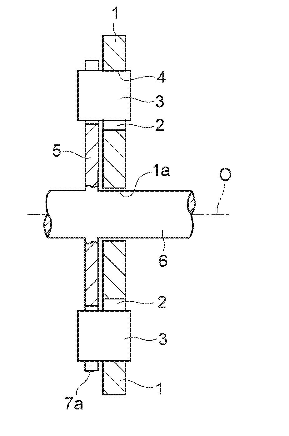
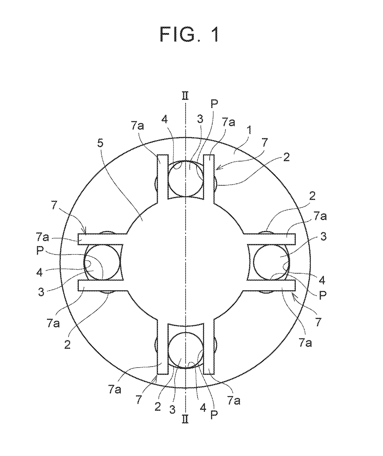
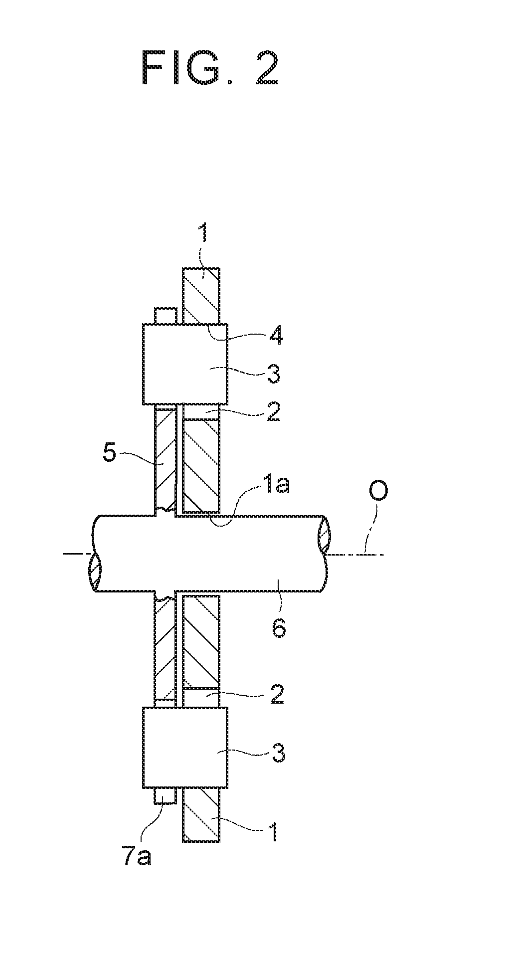
[0041]Next, the disclosure will be described with reference to an embodiment. A torsional vibration reducing device according to an embodiment of the disclosure is configured to rotate an inertial body relative to a rotating body according to torque fluctuation, thereby reducing or suppressing torsional vibration of the rotating body due to the torque fluctuation. FIG. 1 is a front view exemplarily showing a first example of a torsional vibration reducing device according to an embodiment of the disclosure, and FIG. 2 is a sectional view taken along line II-II of FIG. 1. In the example shown here, an inertial body 1 is an annular plate, and a later-described rotary shaft 6 passes through a hole 1a formed at the center of the inertial body 1. Guide holes 2 are formed in the inertial body 1 at regular intervals on the circumference of a circle at positions of the same radius from the rotation center O of the inertial body 1. The guide holes 2 are formed to pass through the inertial bo...


PUM


Abstract

A torsional vibration reducing device includes: a rotating body; an inertial body; a coupling member configured to transmit the torque to the rotating body and to the inertial body; and a first coupling portion and a second coupling portion, which are separately provided to either the rotating body or the inertial body The first coupling portion engages with the coupling member so as to: restrict movement of the coupling member in a rotational direction of the rotating body; and allow movement of the coupling member in a radial direction of the rotating body. The second coupling portion engages with the coupling member such that when the rotating body and the inertial body rotate relative to each other, a contact portion of the coupling member with respect to the first coupling portion moves in the radial direction of the rotating body.

Description

INCORPORATION BY REFERENCE[0001]The disclosure of Japanese Patent Application No. 2016-026845 filed on Feb. 16, 2016 including the specification, drawings and abstract is incorporated herein by reference in its entirety.BACKGROUND[0002]1. Technical Field[0003]The disclosure relates to a torsional vibration reducing device that reduces torsional vibration due to input torque fluctuation.[0004]2. Description of Related Art[0005]An example of this type of device is described in Japanese Patent Application Publication No. 2012-77827. This device includes an annular support member connected to a power source, a plurality of guide holes formed at regular intervals in a circumferential direction of the support member, and a plurality of mass bodies respectively disposed in the guide holes. When the support member rotates, the mass bodies disposed in the guide holes also rotate so that each mass body is pressed against an inner wall surface, on an outer side in a radial direction of the sup...

Claims


Application Information

Patent Timeline
Patent Type & Authority Applications(United States)
IPC IPC(8): F16F15/14
CPCF16F15/145F16F15/1407F16F15/14
Inventor HORITA, SHUHEIAMANO, HIROYUKI
Owner TOYOTA JIDOSHA KK
Why Eureka
Try Eureka