Fault ride-through circuit with variable frequency transformer and control method thereof
a variable frequency transformer and fault ride-through circuit technology, which is applied in the direction of contiguous circuit arrangement, ac network voltage adjustment, single ac network with different frequencies, etc., can solve the problem that limited combinations cannot realize absolute compensation of the vft terminal voltage, vft cannot block grid fault propagation, and breakdown of vft, so as to avoid excessive current wastage, prevent the propagation of voltage dip faults, and avoid the torque fluctuation of v
- Summary
- Abstract
- Description
- Claims
- Application Information
AI Technical Summary
Benefits of technology
Problems solved by technology
Method used
Image
Examples
first embodiment
The First Embodiment
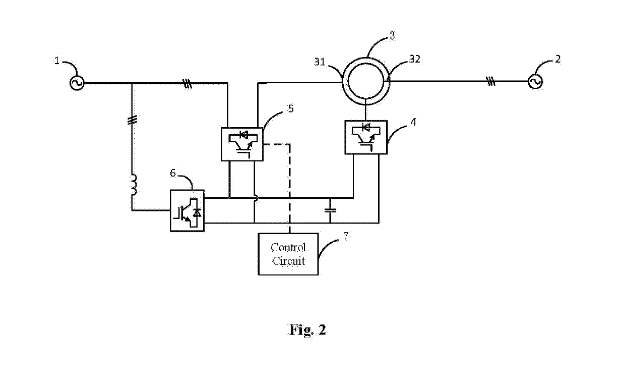
[0039]Referring to FIG. 2, FIG. 2 is a structural schematic diagram of a fault ride-through circuit with a VFT according to an embodiment of the disclosure.
[0040]A fault ride-through circuit with a VFT provided in the disclosure, which could improve the voltage, decrease short-circuit current and prevent the voltage dip fault from propagating to the healthy grid by compensating reactive power, comprises: a first grid 1, a second grid 2, the VFT 3, a first three-phase rectifier 6, a motor-driven convertor 4, a first compensating circuit 5 and a control circuit 7.
[0041]The first grid 1 is connected to an input end of the first three-phase rectifier 6 and a first output end of the first compensating circuit 5, a second output end of the first compensating circuit 5 is connected to a stator interface 31 of the VFT 3, an output end of the first three-phase rectifier 6 is connected to an input end of the first compensating circuit 5 and an input end of the motor-driven...
second embodiment
The Second Embodiment
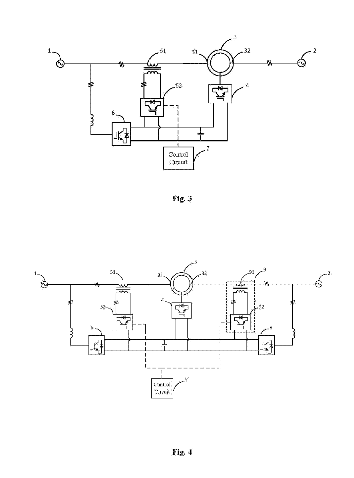
[0055]Referring to FIG. 4, FIG. 4 is a structural schematic diagram of anther fault ride-through circuit with a VFT according to an embodiment of the disclosure.
[0056]The first voltage compensation circuit provided in above embodiment of the present disclosure is one-sided compensation, and cannot solve the voltage dip problem on the other side. Therefore, based on the above embodiment of the first voltage compensation circuit, an additional explanation is added in the present embodiment directed to problem of the voltage dip occurring on both sides. The other parts of the present embodiment are substantially as same as the previous embodiment, which can refer to the previous embodiment, and are not described herein.
[0057]Based on the first embodiment, the fault ride-through circuit with the VFT provided in this embodiment, further comprises: a second three-phase rectifier 8 and a second compensating circuit 9. The second grid 2 is connected to an input end of t...
PUM
 Abstract
Description
Claims
Application Information
 - R&D
- Intellectual Property
- Life Sciences
- Materials
- Tech Scout
- Unparalleled Data Quality
- Higher Quality Content
- 60% Fewer Hallucinations
Browse by: Latest US Patents, China's latest patents, Technical Efficacy Thesaurus, Application Domain, Technology Topic, Popular Technical Reports.
© 2025 PatSnap. All rights reserved.Legal|Privacy policy|Modern Slavery Act Transparency Statement|Sitemap|About US| Contact US: help@patsnap.com


