Torsional compensator based on magnetic reluctance

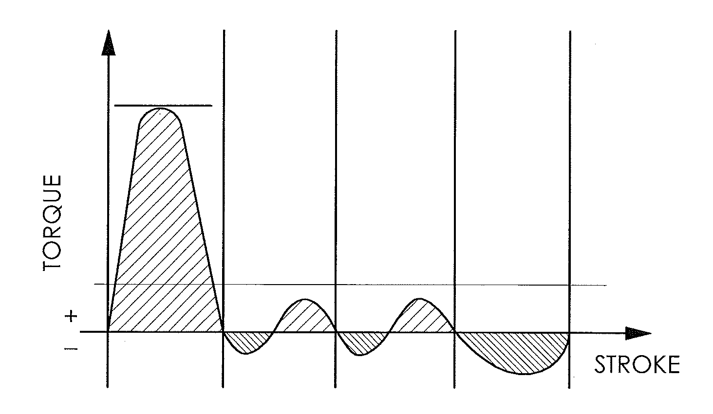
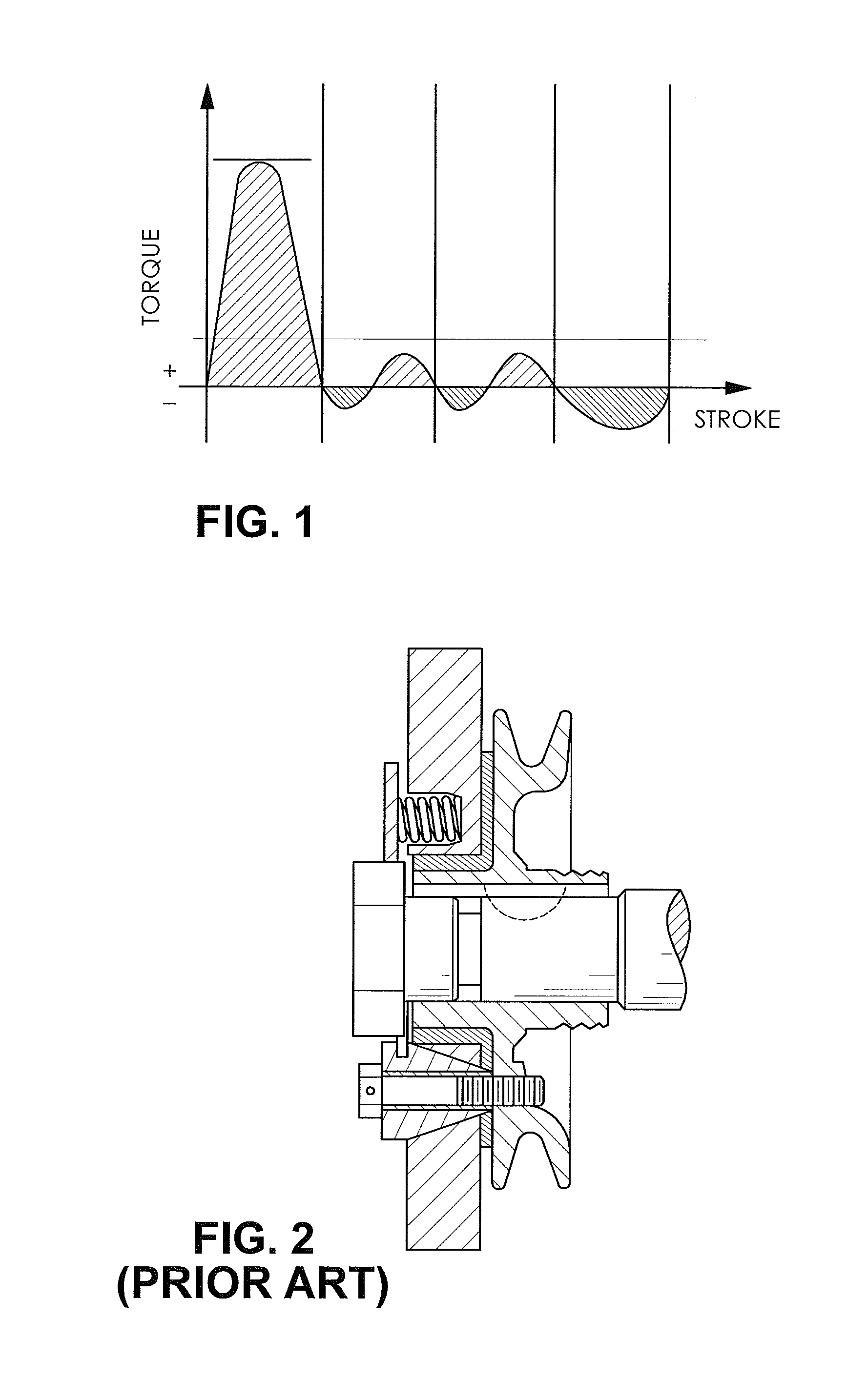
a torsional compensator and magnetic resistance technology, applied in the direction of machines/engines, non-rotating vibration suppression, vibration suppression adjustment, etc., can solve the problems of increased stress on the components, increased wear on the components, and unsatisfactory increase in torque ripple at low operating speed of the engine, so as to dampen the torque ripple of the internal combustion engine

Active Publication Date: 2016-02-11
DANA CORP
View PDF17 Cites 7 Cited by
  • Summary
  • Abstract
  • Description
  • Claims
  • Application Information

AI Technical Summary

Benefits of technology

[0013]In yet another embodiment, the present invention is directed to a torsional compensator for an internal combustion engine. The torsional compensator comprises a first rotor portion, a first stator portion, a second rotor portion, and a second stator portion. The first rotor portion is in driving engagement with an output of the internal combustion engine. The first rotor portion comprises at least one of a first array of permanent magnets and a first ferromagnetic array. The first stator portion is disposed about the first rotor portion. The first stator portion is coupled to at least one of the internal combustion engine, a transmission, and a compensator housing. The first stator portion comprises at least one of a second array of permanent magnets and a second ferromagnetic array. The second rotor portion is in driving engagement with the output of the internal combustion engine. The second rotor portion comprises at least one of a third array of permanent magnets and a third ferromagnetic array. A second stator portion is disposed about the second rotor portion. The second stator portion is coupled to at least one of the internal combustion engine, the transmission, and the compensator housing. The second stator portion comprises at least one of a fourth array of permanent magnets and a fourth ferromagnetic array. In response to rotation of the first rotor portion within the first stator portion and the second rotor portion within the second stator portion, a magnetic reluctance force is generated. The magnetic reluctance force applies a torque to the output of the internal combustion engine to dampen a torque ripple of the internal combustion engine.

Problems solved by technology

In some designs, however, engine down-speeding can result in an undesirable increase in torque ripple at low operating speeds of the engine.
Torque ripples can cause many problems for components of the vehicle near the engine, such as but not limited to: increased stress on the components, increased wear on the components, and exposure of the components to severe vibrations.
These problems can damage a powertrain of the vehicle and result in poor drivability of the vehicle.
A weight of the flywheel, however, can become a factor in such torque ripple compensating devices.
A lighter flywheel accelerates faster but also loses speed quicker, while a heavier flywheel retain speeds better compared to the lighter flywheel, but the heavier flywheel is more difficult to slow down.
However, a heavier flywheel provides a smoother power delivery, but makes an associated engine less responsive, and an ability to precisely control an operating speed of the engine is reduced.

Method used


Image

  • Torsional compensator based on magnetic reluctance
  • Torsional compensator based on magnetic reluctance
  • Torsional compensator based on magnetic reluctance

Examples


Embodiment Construction

[0028]It is to be understood that the invention may assume various alternative orientations and step sequences, except where expressly specified to the contrary. It is also to be understood that the specific devices and processes illustrated in the attached drawings, and described in the following specification are simply exemplary embodiments of the inventive concepts defined herein. Hence, specific dimensions, directions or other physical characteristics relating to the embodiments disclosed are not to be considered as limiting, unless expressly stated otherwise.

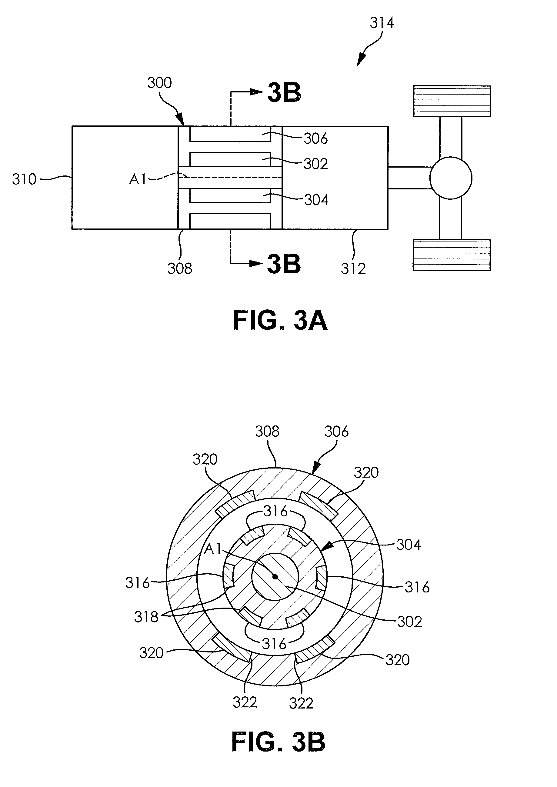
[0029]FIGS. 3A and 3B illustrate a torsional compensator 300. The torsional compensator 300 comprises a central shaft 302, a rotor portion 304, a stator portion 306, and a compensator housing 308. The central shaft 302 is in driving engagement with an internal combustion engine 310 and a transmission 312 of a vehicle driveline 314. The rotor portion 304 is in driving engagement with the central shaft 302. The stator portio...


PUM


Abstract

A torsional compensator for an internal combustion engine is provided. The torsional compensator comprises a rotor portion and a stator portion. The rotor portion is in driving engagement with an output of the internal combustion engine. The first rotor portion comprises at least one of first magnetic array and a first ferromagnetic array. The stator portion is disposed about the rotor portion. The stator portion is coupled to at least one of the internal combustion engine, a transmission, and a compensator housing. The stator portion comprises at least one of a second magnetic array and a second ferromagnetic array. In response to rotation of the rotor portion within the stator portion, a magnetic reluctance force is generated. The magnetic reluctance force applies a torque to the output of the internal combustion engine to dampen a torque ripple of the internal combustion engine.

Description

RELATED APPLICATIONS[0001]The present application claims the benefit of U.S. Provisional Application No. 61 / 814,375 filed on Apr. 22, 2013, which is incorporated herein in its entirety by reference.FIELD OF THE INVENTION[0002]The present invention relates to internal combustion engines and more specifically to a torsional compensator for use with an internal combustion engine.BACKGROUND OF THE INVENTION[0003]Due to recent improvements in combustion engine technology, there has been a trend to downsize internal combustion engines used in vehicles. Such improvements also result in more efficient vehicle, while maintaining similar performance characteristics and vehicle form factors favoured by consumers[0004]One common improvement used with internal combustion engines is the addition of a supercharger or a turbocharger. Typically, the addition of the supercharger or the turbocharger is used to increase a performance of an engine that has been decreased in displacement or a number of e...

Claims


Application Information

Patent Timeline
Patent Type & Authority Applications(United States)
IPC IPC(8): F16F15/03
CPCF16F15/03F16F15/035
Inventor GOOSSENS, STIJNVERSTEYHE, MARK R.J.
Owner DANA CORP
Why Eureka
Try Eureka