Torque fluctuation inhibiting device, torque converter and power transmission device

a technology of torque converter and torque fluctuation, which is applied in the direction of fluid gearing, mechanical equipment, gearing, etc., can solve the problems of difficulty in coping with such requirements, and achieve the effect of reducing the peak torque fluctuation, wide rotational speed range, and inhibiting torque fluctuations

Active Publication Date: 2018-06-14
EXEDY CORP
View PDF0 Cites 7 Cited by
  • Summary
  • Abstract
  • Description
  • Claims
  • Application Information

AI Technical Summary

Benefits of technology

[0039]According to the present advancement described above, in a device for inhibiting torque fluctuations in a rotary member, a peak of torque fluctuations can be reduced in a relatively wide rotational speed range.

Problems solved by technology

However, coping with such requirement may be difficult in some cases.

Method used


Image

  • Torque fluctuation inhibiting device, torque converter and power transmission device
  • Torque fluctuation inhibiting device, torque converter and power transmission device
  • Torque fluctuation inhibiting device, torque converter and power transmission device

Examples


first exemplary embodiment

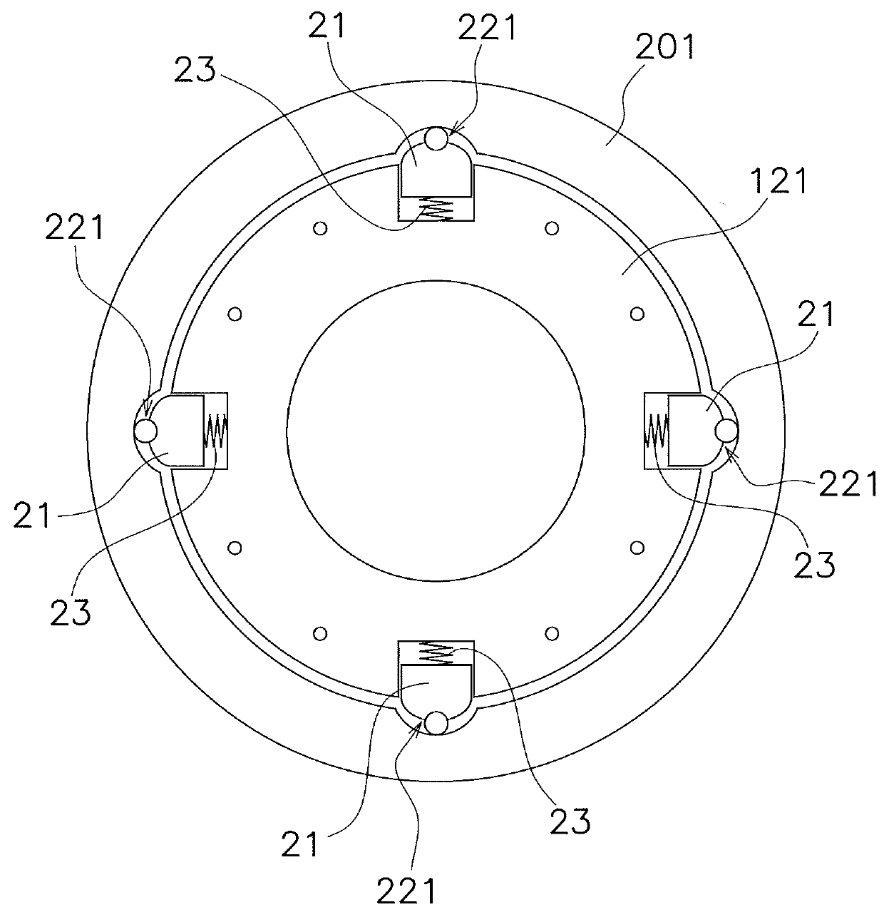
[0076]FIG. 2A is a front view of the first hub 121 and the torque fluctuation inhibiting device 14, whereas FIG. 3A is a front view of the second hub 122 and the torque fluctuation inhibiting device 14. Additionally, part of FIG. 2A is shown close-up in FIG. 4. As shown in these drawings, the torque fluctuation inhibiting device 14 includes first and second inertia rings 201 and 202 composing a mass body 20, a plurality of centrifugal elements 21, four first cam mechanisms 221, four second cam mechanisms 222 and a plurality of coil springs 23. The centrifugal elements 21, the first and second cam mechanisms 221 and 222, and the coil springs 23 are disposed at equal angular intervals of 90 degrees in the circumferential direction, respectively.

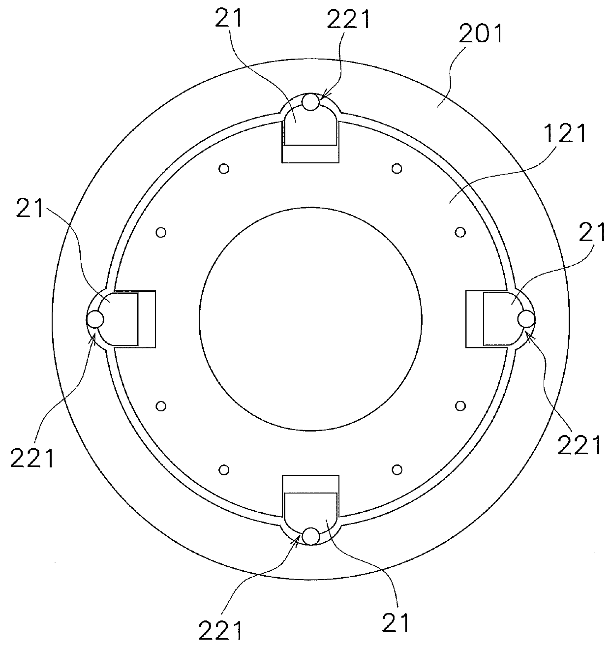
[0077]It should be noted that alternatively, the coil springs 23, disposed on the inner peripheral side of the centrifugal elements 21, respectively, can be omitted as shown in FIGS. 2B and 3B. Likewise, the coil springs 23 can be provided or o...

second exemplary embodiment

[0106]FIGS. 7 and 8 show a torque fluctuation inhibiting device according to a second exemplary embodiment of the present disclosure. In FIG. 7, the first inertia ring 201 is shown in a partially removed state. FIG. 8 is a partial plan view of FIG. 7. It should be noted that a given member, which is the same as or corresponds to a member in the first exemplary embodiment, is assigned and indicated with the same reference sign as the member in the first exemplary embodiment, even when the shape and so forth of the given member are different from those of the member in the first exemplary embodiment.

[0107]The torque fluctuation inhibiting device of the second exemplary embodiment includes the first and second inertia rings 201 and 202, four centrifugal elements 21, two first cam mechanisms 221, two second cam mechanisms 222 and four coil springs 23. The four centrifugal elements 21, the four first cam mechanisms 221 and the four second cam mechanisms 222 are disposed at equal angular ...

third exemplary embodiment

[0117]FIG. 9 shows a torque fluctuation inhibiting device according to a third exemplary embodiment of the present disclosure. It should be noted that a given member, which is the same as or corresponds to a member in the first exemplary embodiment, is assigned and indicated with the same reference sign as the member in the first exemplary embodiment, even when the shape and so forth of the given member are different from those of the member in the first exemplary embodiment.

[0118]The torque fluctuation inhibiting device of the third exemplary embodiment includes the first and second inertia rings 201 and 202, four first centrifugal elements 211, four second centrifugal elements 212, four first cam mechanisms 221, four second cam mechanisms 222 and eight coil springs 23. The four centrifugal elements 211, the four centrifugal elements 212, the four cam mechanisms 221 and the four cam mechanisms 222 are disposed at equal angular intervals of 90 degrees in the circumferential directio...


PUM


Abstract

A torque fluctuation inhibiting device includes a mass body, first and second centrifugal elements, and first and second cam mechanisms. The mass body is rotatable with a rotor and is also rotatable relatively to the rotor. Each of the first and second centrifugal elements receives a centrifugal force to be generated by rotation of the rotor and the mass body. When a relative displacement is produced between the rotor and the mass body in a rotational direction, the first cam mechanism converts the centrifugal force that acts on the first centrifugal element into a first circumferential force directed to reduce the relative displacement. When the relative displacement is produced between the rotor and the mass body in the rotational direction, the second cam mechanism converts the centrifugal force that acts on the second centrifugal element into a second circumferential force directed to reduce the relative displacement.

Description

CROSS-REFERENCES TO RELATED APPLICATIONS[0001]This application is the U.S. National Phase of PCT International Application No. PCT / JP2016 / 071503 filed on Jul. 22, 2016. That application claims priority to Japanese Patent Application No. 2015-162957, filed on Aug. 20, 2015, Japanese Patent Application No. 2015-198244, filed on Oct. 6, 2015, Japanese Patent Application No. 2015-199308, filed on Oct. 7, 2015, and Japanese Patent Application No. 2015-208759, filed on Oct. 23, 2015. The contents of all five applications are herein incorporated by reference in their entirety.BACKGROUNDTechnical Field[0002]The present disclosure relates to a torque fluctuation inhibiting device, particularly to a torque fluctuation inhibiting device for inhibiting torque fluctuations in a rotor to which a torque is inputted. Additionally, the present disclosure relates to a torque converter and a power transmission device, each of which includes the torque fluctuation inhibiting device.Background Art[0003]...

Claims


Application Information

Patent Timeline
Patent Type & Authority Applications(United States)
IPC IPC(8): F16F15/14F16H45/02F16F15/31
CPCF16F15/145F16H45/02F16F15/31F16H2045/0263F16H41/24F16H2045/0205F16H2045/0221F16F15/13128F16F15/134F16F15/14F16H2045/0273Y10T74/2121Y10T74/2128F16F15/123F16F15/13469F16H25/18F16H2045/0231F16F15/1457
Inventor TOMIYAMA, NAOKIHAGIHARA, YOSHIYUKIHIGUCHI, KOICHI
Owner EXEDY CORP
Why Eureka
Try Eureka