Vibration damper for boom system, boom system and pumping machinery

The technology of a vibration damping device and a boom is applied to the vibration damping device of the boom system and the field of pumping machinery, which can solve the problems of complex movement mode and structure, and unsatisfactory vibration damping effect, so as to offset the initial vibration and ensure the stability. Effect

Inactive Publication Date: 2010-11-17
SANY HEAVY IND CO LTD (CN)
View PDF9 Cites 18 Cited by
  • Summary
  • Abstract
  • Description
  • Claims
  • Application Information

AI Technical Summary

Problems solved by technology

In practical application, the vibration reduction effect of the above technical solution is not ideal, and the movement mode and structure are also very complicated

Method used


Image

  • Vibration damper for boom system, boom system and pumping machinery
  • Vibration damper for boom system, boom system and pumping machinery
  • Vibration damper for boom system, boom system and pumping machinery

Examples


Embodiment 1

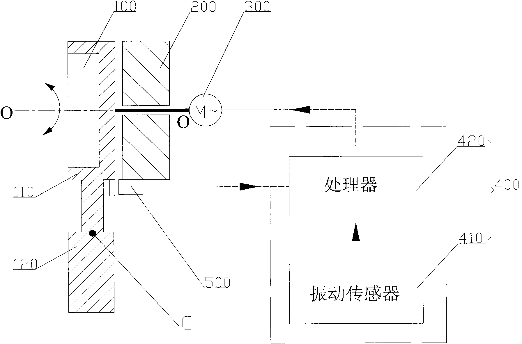
[0039] The vibration damping device provided in Embodiment 1 includes a rotating body 100, a main body 200, a speed-regulating motor 300 and a control mechanism 400; the main body 200 is installed on the jib system, specifically, it can be installed on the corresponding section arm of the jib system; the rotating body 100 It is rotatably installed on the body 200, so that the rotating body 100 can rotate around the rotation axis O-O relative to the body 200; the speed regulating motor 300 is relatively fixed with the body 200, and its output shaft is connected with the rotating body 100. When the speed motor 300 rotates, it can drive the rotating body 100 to rotate around the rotation axis O-O relative to the main body 200 . At the same time, the center of gravity G of the rotating body 100 deviates from the rotating axis O-O to form a suitable eccentricity; in this way, during the rotation of the rotating body 100, a pulsating impact will be generated on the main body 200, res...

Embodiment 2

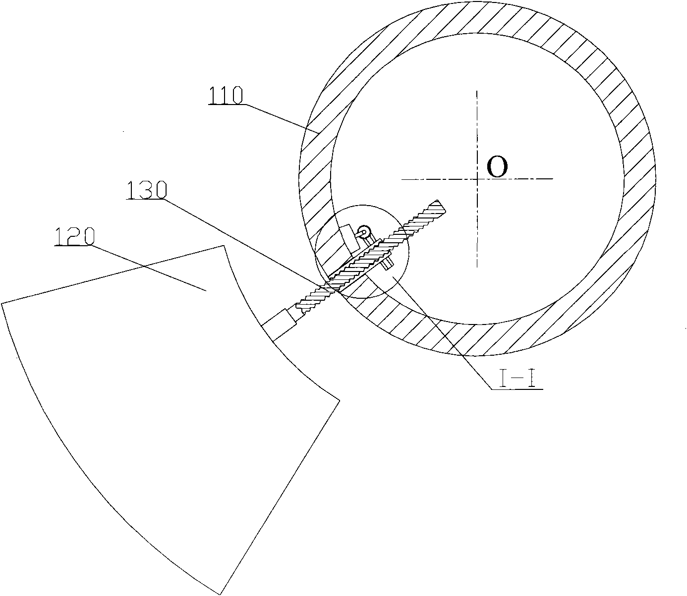
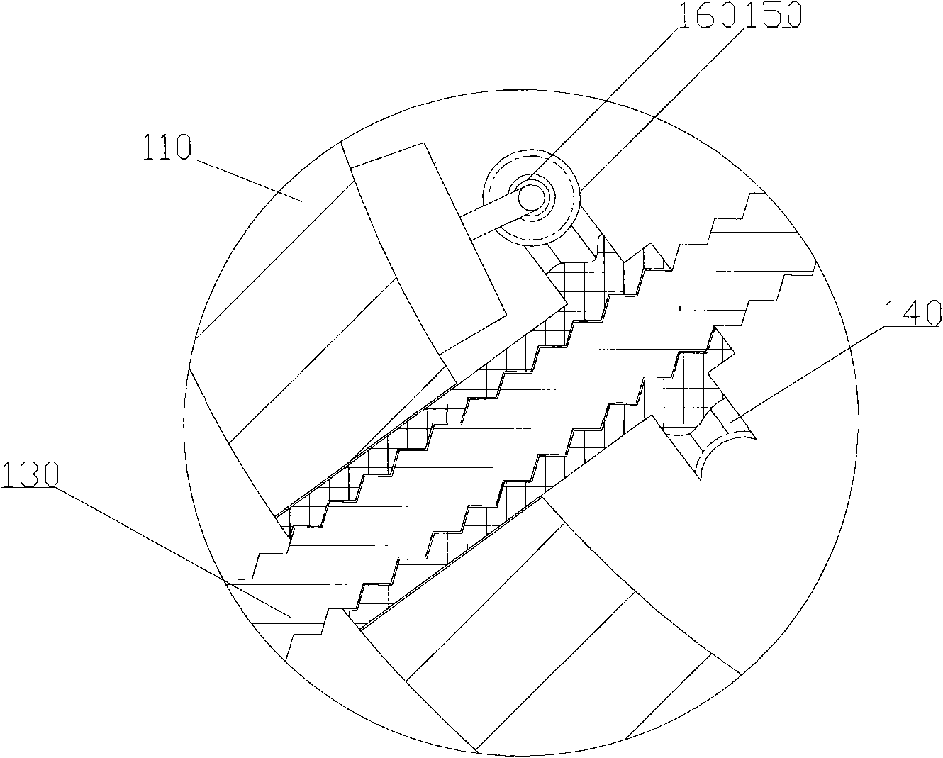
[0059] In the second embodiment, the distance adjustment mechanism of the rotating body 100 includes a screw rod 130 , a worm wheel 140 , a worm 150 and a distance adjustment motor 160 . The worm wheel 140 and the worm 150 cooperate, and the two are respectively rotatably installed on the rotating base 110 . The output shaft of the distance adjusting motor 160 is connected with the worm 150 , and the worm wheel 140 can be driven to rotate through the worm 150 . One end of the screw rod 130 is connected to the worm wheel 140 through a transmission thread, and the other end is connected to the eccentric weight 120 ; In this way, when the pitch-adjusting motor 160 is started, the worm wheel 140 can drive the screw rod 130 to move in the axial direction through the transmission thread when the worm wheel 150 can drive the worm wheel 140 to rotate, thereby changing the distance between the eccentric weight 120 and the rotation axis O-O, realizing The adjustment of the position of ...


PUM


Abstract

The invention discloses pumping machinery, a boom system of the pumping machinery, and a vibration damper for the boom system. The vibration damper for the boom system comprises a main body, a rotating body, an adjustable speed motor and a control mechanism, wherein, the main body is installed on the boom system, the rotating body is rotatablely installed on the main body, the adjustable speed motor drives the rotating body to rotate around a rotation axis relative to the main body, and the gravity center of the rotating body deviates from the rotation axis; the control mechanism comprises a vibration sensor and a processor, the vibration sensor can detect initial vibration of the boom system, and the processor can command the adjustable speed motor to operate according to an initial vibration signal detected by the vibration sensor so as to drive the rotating body to rotate and generate leveling vibration; and the vibrating direction of leveling vibration is opposite to that of initial vibration by regulating the rotating parameters of the adjustable speed motor. By using the vibration damper, at least part of initial vibration of the boom system can be offset, thus further reducing vibration of the boom system.

Description

technical field [0001] The invention relates to a technology for pumping viscous fluids such as concrete, in particular to a vibration damping device for a boom system, the boom system, and a pumping machine with the boom system. Background technique [0002] Concrete pump truck is one of the most widely used pumping machinery at present. Concrete pump trucks generally include pumping devices and boom systems. The pumping device generally includes a hopper, a delivery cylinder and a distribution valve. The boom system includes a boom and a conveying pipe. The boom consists of a multi-section boom connected sequentially through a horizontal hinge shaft. Position; the conveying pipe includes a plurality of sequentially connected pipes, and the pipes are respectively fixed on the corresponding section arms. The hopper is used to store concrete; the distributing valve can be driven by the swing cylinder to switch states, connect the conveying cylinder with the hopper within t...

Claims


Application Information

Patent Timeline
Patent Type & Authority Applications(China)
IPC IPC(8): E04G21/02F16F15/02
CPCE04G21/0454B66C13/066F16F15/22
Inventor 周翔喻志平
Owner SANY HEAVY IND CO LTD (CN)
Why Eureka
Try Eureka