Test device for testing distance between centers of two through holes

Inactive Publication Date: 2012-10-25
HONG FU JIN PRECISION IND (SHENZHEN) CO LTD +1
View PDF13 Cites 13 Cited by
  • Summary
  • Abstract
  • Description
  • Claims
  • Application Information

AI Technical Summary

Problems solved by technology

However, due to the complicated operation of the caliper

Method used


Image

  • Test device for testing distance between centers of two through holes
  • Test device for testing distance between centers of two through holes
  • Test device for testing distance between centers of two through holes

Examples


Embodiment Construction

[0011]The present disclosure, including the accompanying drawings, is illustrated by way of examples and not by way of limitation. It should be noted that references to “an” or “one” embodiment in this disclosure are not necessarily to the same embodiment, and such references mean at least one.

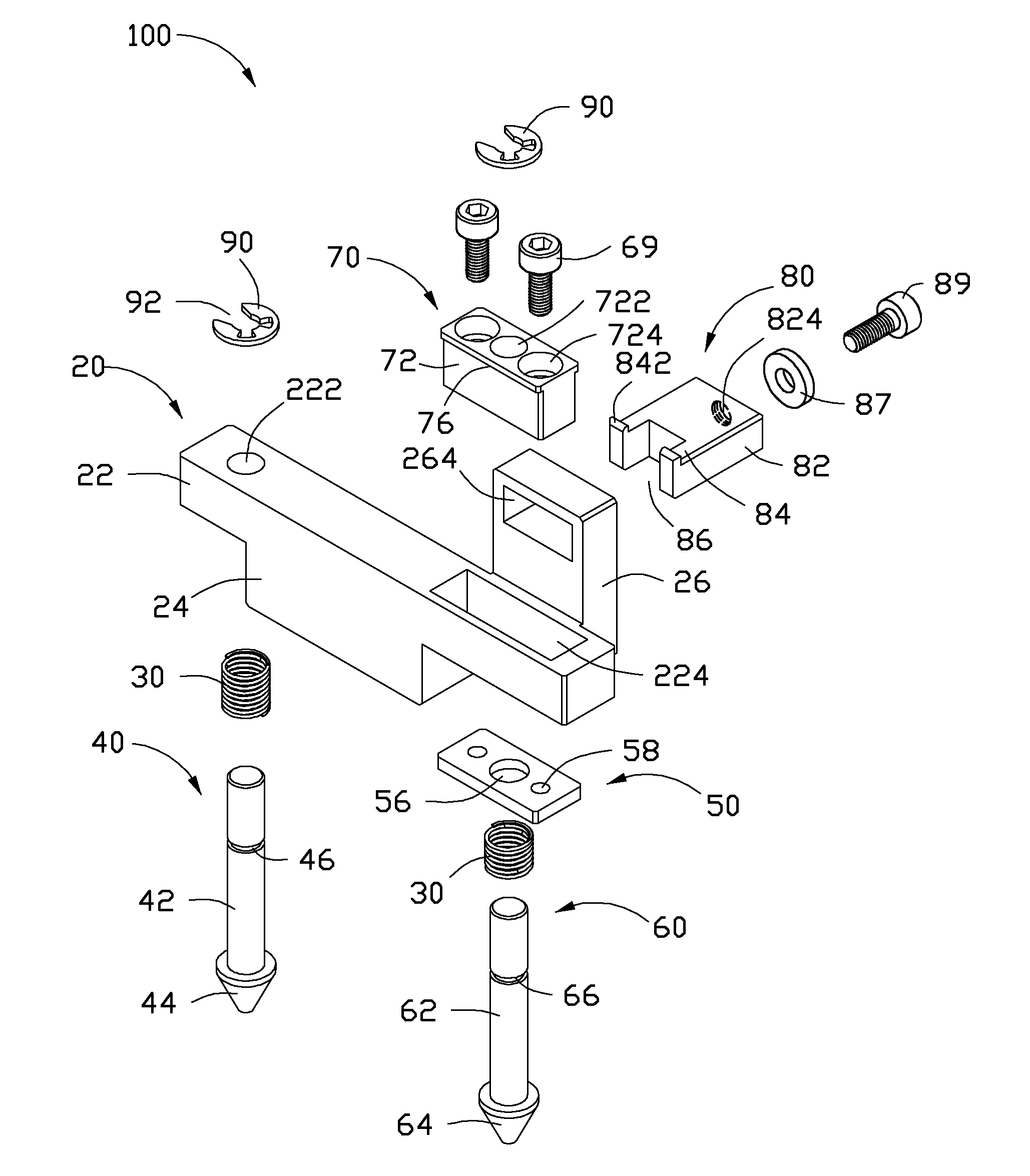
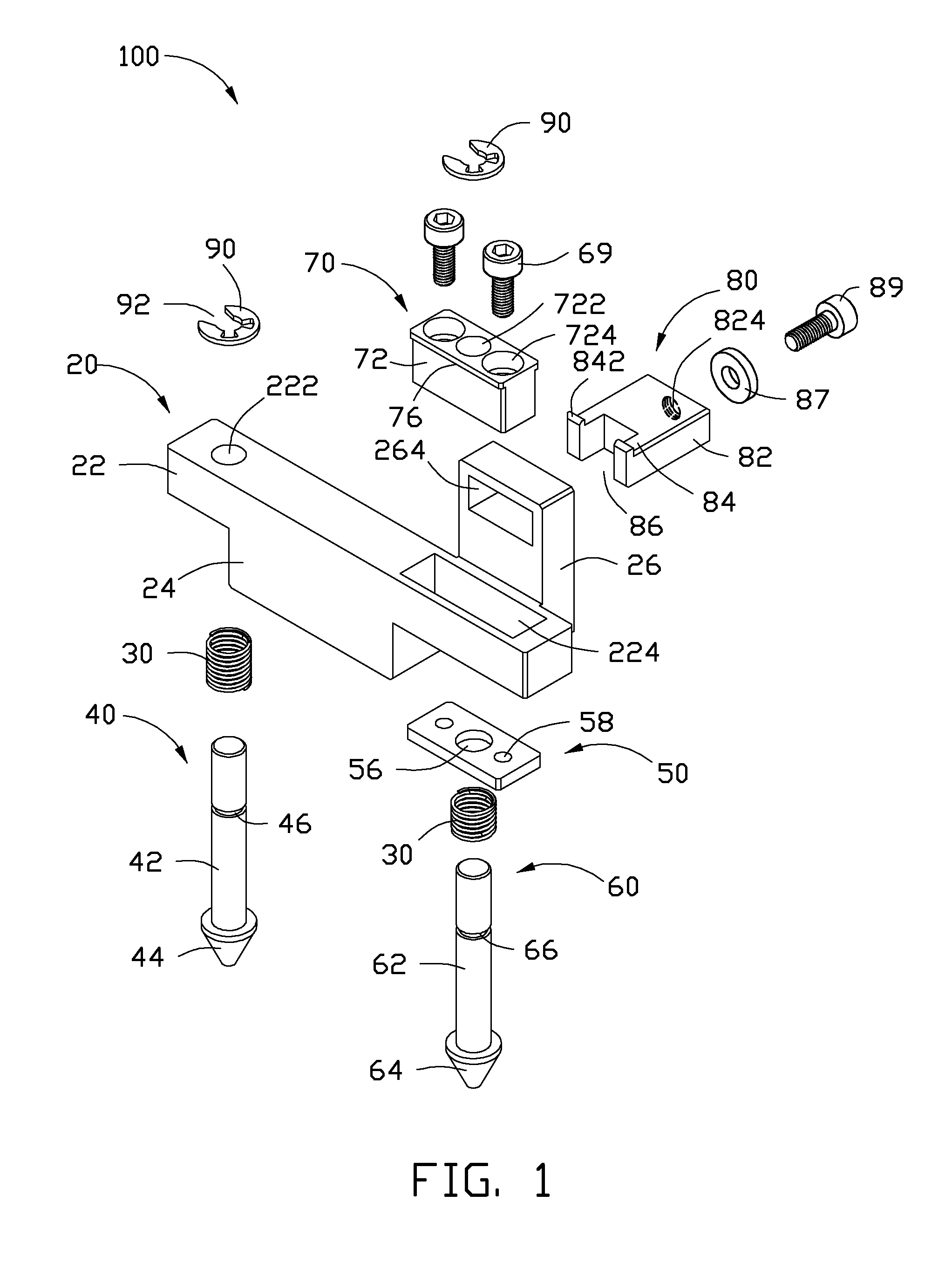
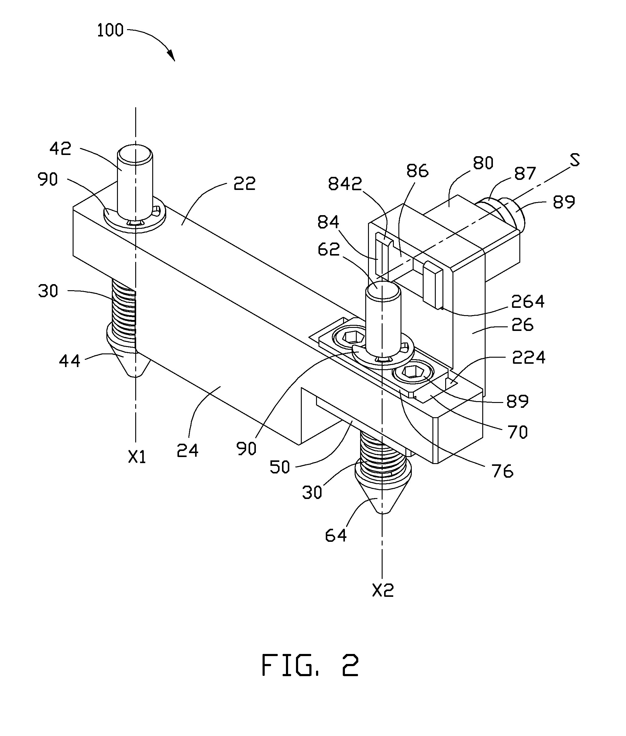
[0012]Referring to FIGS. 1-3, an exemplary embodiment of a test device 100 tests whether the distance “W” between the center O1 of a first through hole 312 and the center O2 of a second through hole 314 defined in an article 300 meets specifications. The specification distance between the center O1 and the center O2 is “L”, a permissible error is “a”. The center O1 of the first through hole 312 and the center O2 of the second through hole 314 must meet a determined specification that the distance between the centers O1 and O2 is within the range of “W=L±a”. The test device 100 includes a supporting member 20, two elastic members 30, a benchmark member 40, a connecting plate 50, a test member 6...


PUM


Abstract

A test device for testing whether the distance between centers meets specifications includes a support member, a benchmark member set on a first end of the support member, to be positioned at the first through hole, a test member set on a second end of the support member, to be positioned at the second through hole, and a sliding member defining a receiving slot. The test member is also slidable in a direction perpendicular to the slidable direction of the test member. If the test member can enter the receiving slot, the first article is qualified, if test member cannot enter the receiving slot, the second article does not meet the required standard.

Description

BACKGROUND[0001]1. Technical Field[0002]The present disclosure relates to test devices, and particularly, to a device for testing the distance between centers of two through holes.[0003]2. Description of Related Art[0004]In machining, a lot of through holes are created in workpieces. To ensure that the distance between two adjacent through holes meets a specification, a caliper is generally used for testing the distance. However, due to the complicated operation of the caliper and human error, the reliability of the test is reduced.BRIEF DESCRIPTION OF THE DRAWINGS[0005]Many aspects of the present embodiments can be better understood with reference to the following drawings. The components in the drawings are not necessarily drawn to scale, the emphasis instead being placed upon clearly illustrating the principles of the present embodiments. Moreover, in the drawings, all the views are schematic, and like reference numerals designate corresponding parts throughout the several views....

Claims


Application Information

Patent Timeline
IPC IPC(8): B25H7/00
CPCG01B5/143
Inventor ZHANG, BING-JUN
Owner HONG FU JIN PRECISION IND (SHENZHEN) CO LTD
Why Eureka
Try Eureka