Light source apparatus and image display apparatus

a technology of light source apparatus and image display device, which is applied in the direction of lighting and heating apparatus, instruments, optics, etc., can solve the problems of difficult to obtain high-output red light with the conventional light source apparatus, and difficulty in obtaining high-output red ligh

Active Publication Date: 2012-10-25
PANASONIC CORP
View PDF7 Cites 50 Cited by
  • Summary
  • Abstract
  • Description
  • Claims
  • Application Information

AI Technical Summary

Benefits of technology

[0036]The invention makes it possible to achieve a high-brightness and low-noise light source apparatus using a long-life and mercury-free solid light source. Further, it is possible to provide a high-image-quality image display apparatus using the light source apparatus.

Problems solved by technology

A red phosphor for obtaining red light, however, has a greater problem with the lifetime of fluorescence and temperature quenching than a green phosphor for obtaining a green light, which makes it difficult to obtain red output light having a high brightness and a high efficiency.
Consequently, it is difficult to obtain high-output red light with the conventional light source apparatus.

Method used


Image

  • Light source apparatus and image display apparatus
  • Light source apparatus and image display apparatus
  • Light source apparatus and image display apparatus

Examples


embodiment 1

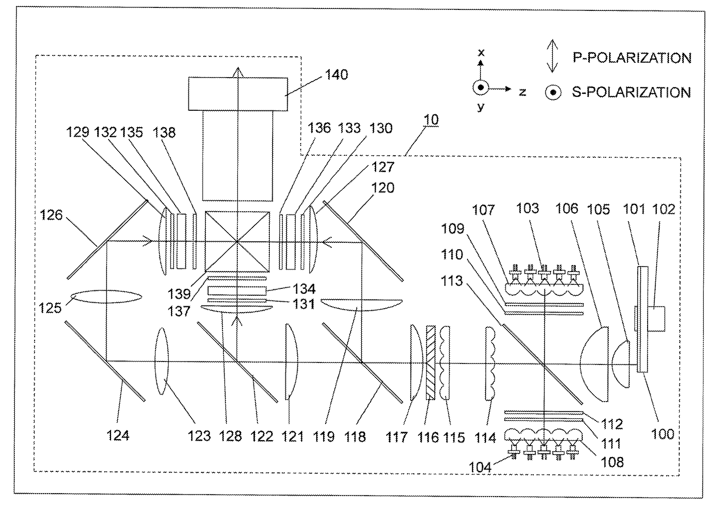
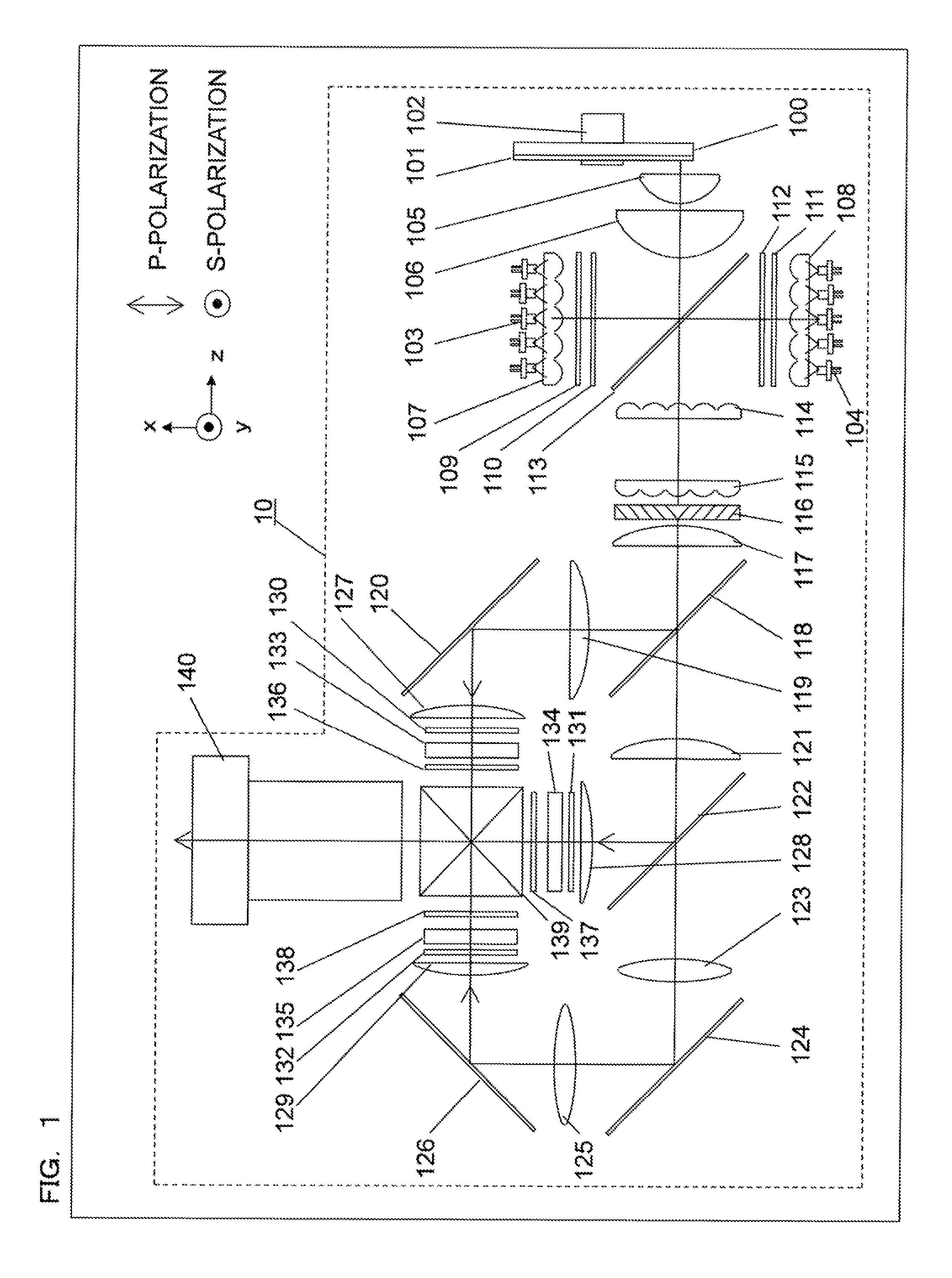
[0047]FIG. 1 shows a structural diagram of a light source apparatus and an image display apparatus using the light source apparatus according to a first embodiment.

[0048]The structure of an image display apparatus 10 according to the present embodiment is as follows.

[0049]A substrate 100 is a circular piece of plane parallel glass, and is coated with dichroic coating on the surface on one side thereof, the dichroic coating reflecting light in the entire visible light range with a high efficiency. Additionally, a phosphor 101 is applied as a thin film further to the dichroic coating, and emits fluorescence having wavelengths of green as a main wavelength region of fluorescence. The substrate 100 is attached to rotation means 102 so as to be controlled to rotate. With xyz coordinate axes defined as shown in FIG. 1, the substrate 100 rotates about a rotating shaft parallel to the z-axis. The number of rotations of the substrate 100 is not particularly limited, but is preferably 1000 rp...

embodiment 2

[0080]FIG. 6 shows a structural diagram of a light source apparatus and an image display apparatus using the light source apparatus according to a second embodiment. Some of the components of the present embodiment are the same as those of the first embodiment, and therefore are not described here.

[0081]The structure of an image display apparatus 20 according to the present embodiment is as follows.

[0082]A substrate 200, a phosphor 201, and rotation means 202 employed in the present embodiment are the same as those of the first embodiment. A phosphor is applied annularly about the rotating shaft, of the substrate 200, parallel to the x-axis.

[0083]An excitation light source 203, a collimating lens array 207, a red laser light source 204, and a collimating lens array 208 are also the same as those of the first embodiment. The entirety of the collimated blue laser light, however, is adjusted to be P-polarized light, passes through a diffusion plate 209, and is subsequently made inciden...

embodiment 3

[0098]FIG. 9 shows a structural diagram of a light source apparatus and an image display apparatus using the light source apparatus according to a third embodiment. Some of the components of the present embodiment are the same as those of the first embodiment, and therefore are not described here.

[0099]The structure of an image display apparatus 30 according to the present embodiment is as follows.

[0100]A substrate 300, a phosphor 301, and rotation means 302 employed in the present embodiment are the same as those of the first embodiment. A yellow phosphor is applied annularly about the rotating shaft, of the substrate 300, parallel to the z-axis. The yellow phosphor may be a YAG (yttrium-aluminum-garnet) phosphor material, for example.

[0101]An excitation light source 303 and a collimating lens array 307 are also the same as those of the first embodiment. The entirety of the collimated blue laser light is adjusted to be S-polarized light, passes through a diffusion plate 310, and is...


PUM


Abstract

A light source apparatus includes: an excitation light source; a phosphor having, as a main fluorescence wavelength region, wavelengths of green excited by excitation light emitted from the excitation light source; a red laser light source that oscillates in a red wavelength region; an optical multiplexer that multiplexes fluorescence emitted from the phosphor and red laser light emitted from the red laser light source; and color demultiplexing optics that demultiplexes the multiplexed light into two light beams. A cutoff wavelength of the color demultiplexing optics is a wavelength in the wavelength region of fluorescence, and is shorter than the red wavelength region.

Description

BACKGROUND OF THE INVENTION[0001]1. Field of the Invention[0002]The present invention relates to a light source apparatus using lasers and a phosphor, and in particular, relates to a light source apparatus that emits visible light such as red, green, and blue light to be used in an image display apparatus, and also to an image display apparatus using the light source apparatus.[0003]2. Description of the Background Art[0004]Today, a projector is widely used as an image display apparatus that projects various video images and the like onto a screen in an enlarged manner. The projector causes a spatial light modulation device, such as a digital micromirror device (DMD) or a liquid crystal display device, to collect the light emitted from a light source, and causes the light modulated with a video signal and emitted from the spatial light modulation device, to be displayed as a color video image on the screen.[0005]To obtain a bright large-screen video image in the projector, a high-pr...

Claims


Application Information

Patent Timeline
Patent Type & Authority Applications(United States)
IPC IPC(8): F21V9/16
CPCH04N9/3105H04N9/3158H04N9/3164H04N9/3161G03B21/204G03B21/2073G03B33/12G03B21/2013
Inventor KITANO, HIROSHITANAKA, TAKAAKI
Owner PANASONIC CORP
Why Eureka
Try Eureka