Wide bandwidth integrated 2x4 RF divider

a power divider and wide bandwidth technology, applied in waveguides, polarised antenna unit combinations, electrical devices, etc., can solve the problems of large resistive load, high insertion loss of 24 dividers, and large resistive load of power dividers comprising 180-degree hybrids

Active Publication Date: 2012-11-01
TOYON RES CORP
View PDF3 Cites 3 Cited by
  • Summary
  • Abstract
  • Description
  • Claims
  • Application Information

AI Technical Summary

Problems solved by technology

Power dividers comprising 180-degree hybrids, resistive loads, and impedance transformers tend to be large, especially at low frequencies; partially due to the fact that 180-degree hybrids are bulky devices.
Moreover, such 2×4 dividers have high insertion losses and the two resistive loads do not serve any purpose for applications where the divider feeds into a symmetric device.

Method used


Image

  • Wide bandwidth integrated 2x4 RF divider
  • Wide bandwidth integrated 2x4 RF divider
  • Wide bandwidth integrated 2x4 RF divider

Examples


Embodiment Construction

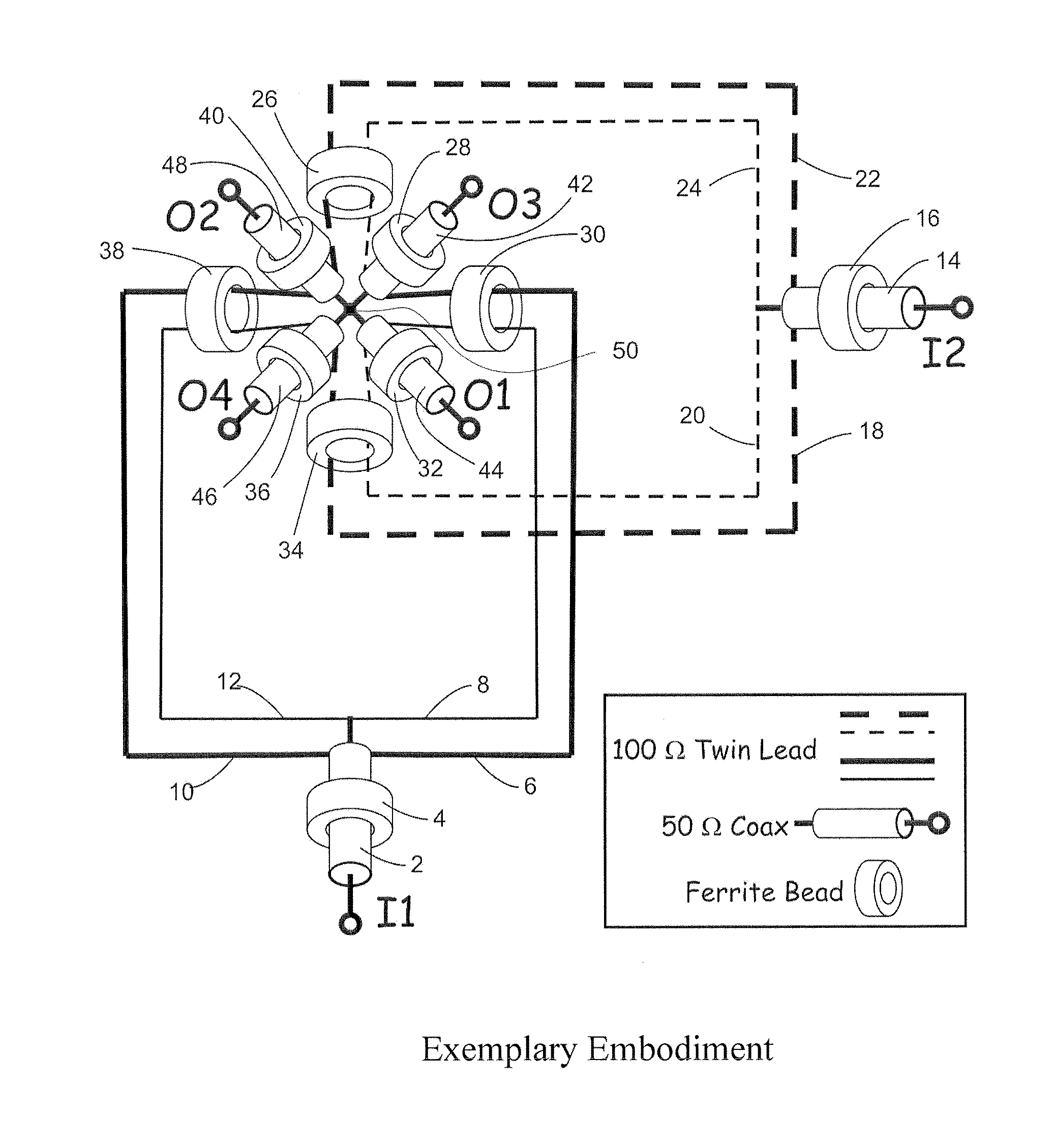
[0023]A preferred embodiment of our 2×4 divider is illustrated in FIG. 5. At the 2×4 divider input, I1, the RF signal enters the 2×4 divider via a 50-ohm UT-085 semi-rigid coaxial transmission line 2 which is passed thru a slide fitting SB-801-61 ferrite bead 4 and split into two twin-lead transmission lines formed by the 20-gauge pair of wires 6 and 8 and the 20-gauge pair of wires 10 and 12. The insulation is removed from wire 6 and from wire 10 to fit within SB-801-61 ferrite beads 30 and 38 and also to form a 100-ohm transmission line within those ferrite beads. Since the pair of 100-ohm twin-lead transmission lines are connected in parallel, together they present a 50-ohm impedance match to the input coaxial transmission line. It is important to minimize the lengths of wire that are located outside the ferrite beads, since those lengths of wire contribute spurious reactance that can limit the upper frequency range of the 2×4 divider.

[0024]After passing thru ferrite beads 30 and...


PUM


Abstract

An improved implementation of a 2×4 divider formed from a bridge junction is described. The bridge junction uses parallel and series connections of coaxial lines to eliminate impedance transformers that are normally required in a 2×4 power divider. In a preferred embodiment, the bridge junction is comprised of UT-085 coax transmission lines, 20 gauge twin lead wire and SB-805-61 ferrite beads with ½ turn windings to provide a wide bandwidth, compact, high power and rugged arrangement.

Description

RELATED APPLICATIONS[0001]This non-provisional application claims priority rights pursuant to 35 U.S.C. §119(e) based on U.S. Provisional Application Ser. No. 61 / 480,260, filed Apr. 28, 2011, the entire content of which is hereby incorporated by reference.BACKGROUND[0002]1. Technical Field[0003]The present application relates to the field of radio frequency (RF) power dividers and more particularly relates to a class of 2×4 power dividers that produce two pairs of differential unbalanced outputs from two unbalanced inputs.[0004]2. Background[0005]The general input-output relationship of a 2×4 divider, which has two input ports labeled I1 and I2, and four output ports labeled O1, O2, O3, and O4, is shown in FIG. 1. The relative phase of the ports is indicated by FIG. 1 and in the following:Phase (deg)PortO1O2O3O4I101801800I201800180[0006]In the current state of the art, 2×4 dividers are built using a corporate connection of three 180-degree hybrids as depicted in FIG. 2. The general ...

Claims


Application Information

Patent Timeline
Patent Type & Authority Applications(United States)
IPC IPC(8): H01P5/12
CPCH01Q21/24H01P5/12
Inventor GILBERT, MICHAEL A.HIGGINS, KEVIN C.HAMILL, ANDREW I.
Owner TOYON RES CORP
Why Eureka
Try Eureka