Driving Method of Display Device
a display device and driving method technology, applied in static indicating devices, instruments, electroluminescent light sources, etc., can solve the problems that none of them have provided a sufficient effect for reducing pseudo contours, and achieve the effects of improving display quality, clear image, and reducing pseudo contours
- Summary
- Abstract
- Description
- Claims
- Application Information
AI Technical Summary
Benefits of technology
Problems solved by technology
Method used
Image
Examples
embodiment mode 1
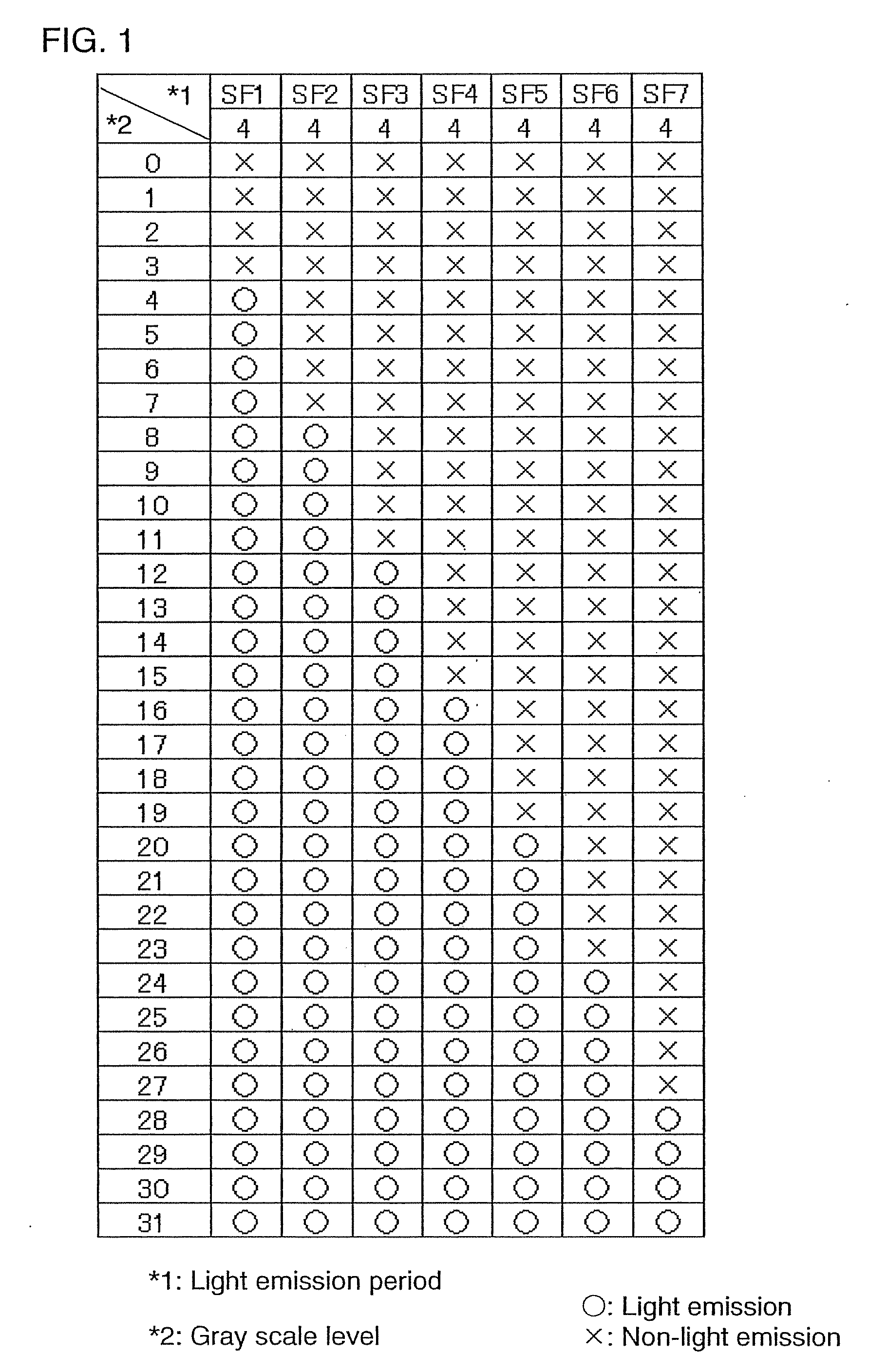
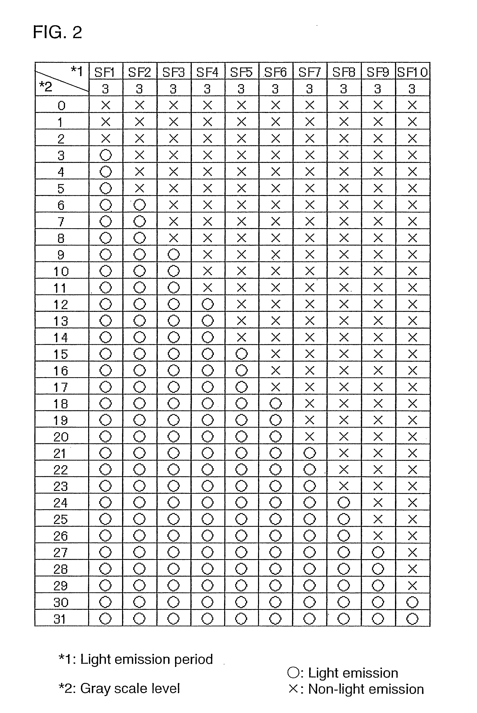
[0065]Here, for example, 5-bit gray scale is expressed. That is, description is made on the case of 32 gray scale levels.
[0066]According to the invention, gray scale is expressed by sequentially adding light emission period of each subframe (or the number of light emission in a certain time). That is, the higher the gray scale is, the light emitting element emits light in more subframes. Therefore, the subframe in a light emission state in the low gray scale level is also in light emission state in the high gray scale level. Such a gray scale method is referred to as a superimpose time gray scale method. By the superimpose time gray scale method, whole gray scale levels are expressed.
[0067]Next, description is made on a method for selecting a subframe in each gray scale level, that is, whether each subframe emits light or not in each gray scale level. FIG. 1 shows a method for selecting subframes in the case where one frame is formed of seven subframes. Accordingly, 3-bit, namely ei...
embodiment mode 2
[0115]Hereinafter described in this embodiment mode are configurations of a display device, a signal line driver circuit, a gate line driver circuit, and the like, and operations thereof.
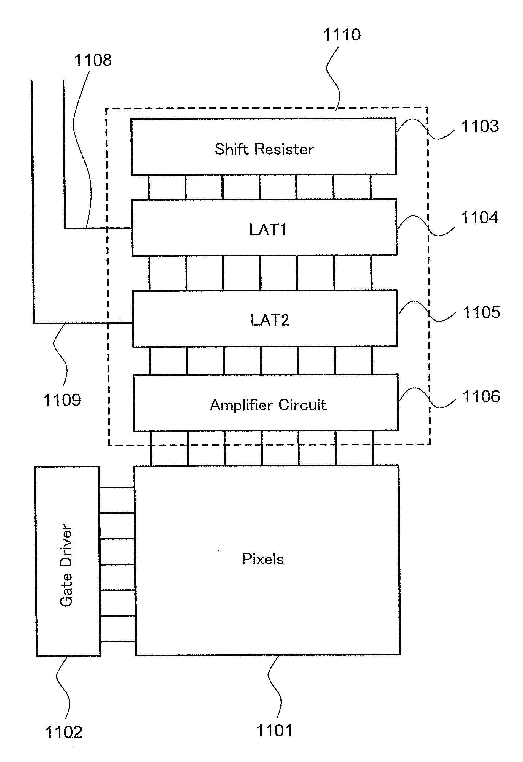
[0116]A display device includes a pixel portion 1101, a gate line driver circuit 1102, and a signal line driver circuit 1110 as shown in FIG. 11. The gate line driver circuit 1102 sequentially outputs selection signals to the pixel portion 1101. The gate line driver circuit 1102 is formed of a shift register, a buffer circuit, and the like.
[0117]Besides, the gate line driver circuit 1102 often includes a level shifter circuit, a pulse width control circuit and the like. The shift register outputs pulses for sequential selection. The signal line driver circuit 1110 sequentially outputs video signals to the pixel portion 1101. The shift register 1103 outputs pulses for sequential selection. The pixel portion 1101 displays an image by controlling a state of light in accordance with the video signals. T...
embodiment mode 3
[0129]Next, description is made on a layout of a pixel of a display device of the invention. As an example, FIG. 13 shows a layout of the circuit diagram shown in FIG. 10. Similarly, FIG. 14 shows a layout of the circuit diagram shown in FIG. 9. It is to be noted that the circuit diagram and the layout are not limited to FIGS. 10, 9, 13, and 14.
[0130]First, FIG. 13 is referred. FIG. 13 includes a selecting transistor 1301, a driving transistor 1303, a diode-connected erasing transistor 1311, and an electrode 1304 of a display element. A source and a drain of the selecting transistor 1301 are connected to a signal line 1305 and a gate of the driving transistor 1303 respectively. A gate of the selecting transistor 1301 is connected to a first gate line 1307. A source and a drain of the driving transistor 1303 are connected to a power source line 1306 and the electrode 1304 respectively. The diode-connected erasing transistor 1311 is connected to the gate of the driving transistor 1303...
PUM
 Abstract
Description
Claims
Application Information
 - R&D
- Intellectual Property
- Life Sciences
- Materials
- Tech Scout
- Unparalleled Data Quality
- Higher Quality Content
- 60% Fewer Hallucinations
Browse by: Latest US Patents, China's latest patents, Technical Efficacy Thesaurus, Application Domain, Technology Topic, Popular Technical Reports.
© 2025 PatSnap. All rights reserved.Legal|Privacy policy|Modern Slavery Act Transparency Statement|Sitemap|About US| Contact US: help@patsnap.com


