Display device having a plurality of subframes and method of driving the same

a display device and subframe technology, applied in static indicating devices, instruments, electroluminescent light sources, etc., can solve the problems that none of them have provided a sufficient effect for reducing pseudo contours, and achieve the effects of improving display quality, clear image, and reducing pseudo contours

Active Publication Date: 2013-02-19
SEMICON ENERGY LAB CO LTD
View PDF97 Cites 1 Cited by
  • Summary
  • Abstract
  • Description
  • Claims
  • Application Information

AI Technical Summary

Benefits of technology

The invention provides a display device and a driving method that can reduce pseudo contour and improve display quality while reducing power consumption. This is achieved by adding the weight of each subframe to express the gray scale in an intermediate level using a binary value, and by erasing the signal stored in a pixel using a diode. The invention can prevent the generation of pseudo contour, resulting in a clear image.

Problems solved by technology

In this manner, various methods for suppressing pseudo contour have been suggested, however, none of them have provided a sufficient effect for reducing pseudo contour.

Method used


Image

  • Display device having a plurality of subframes and method of driving the same
  • Display device having a plurality of subframes and method of driving the same
  • Display device having a plurality of subframes and method of driving the same

Examples


embodiment mode 1

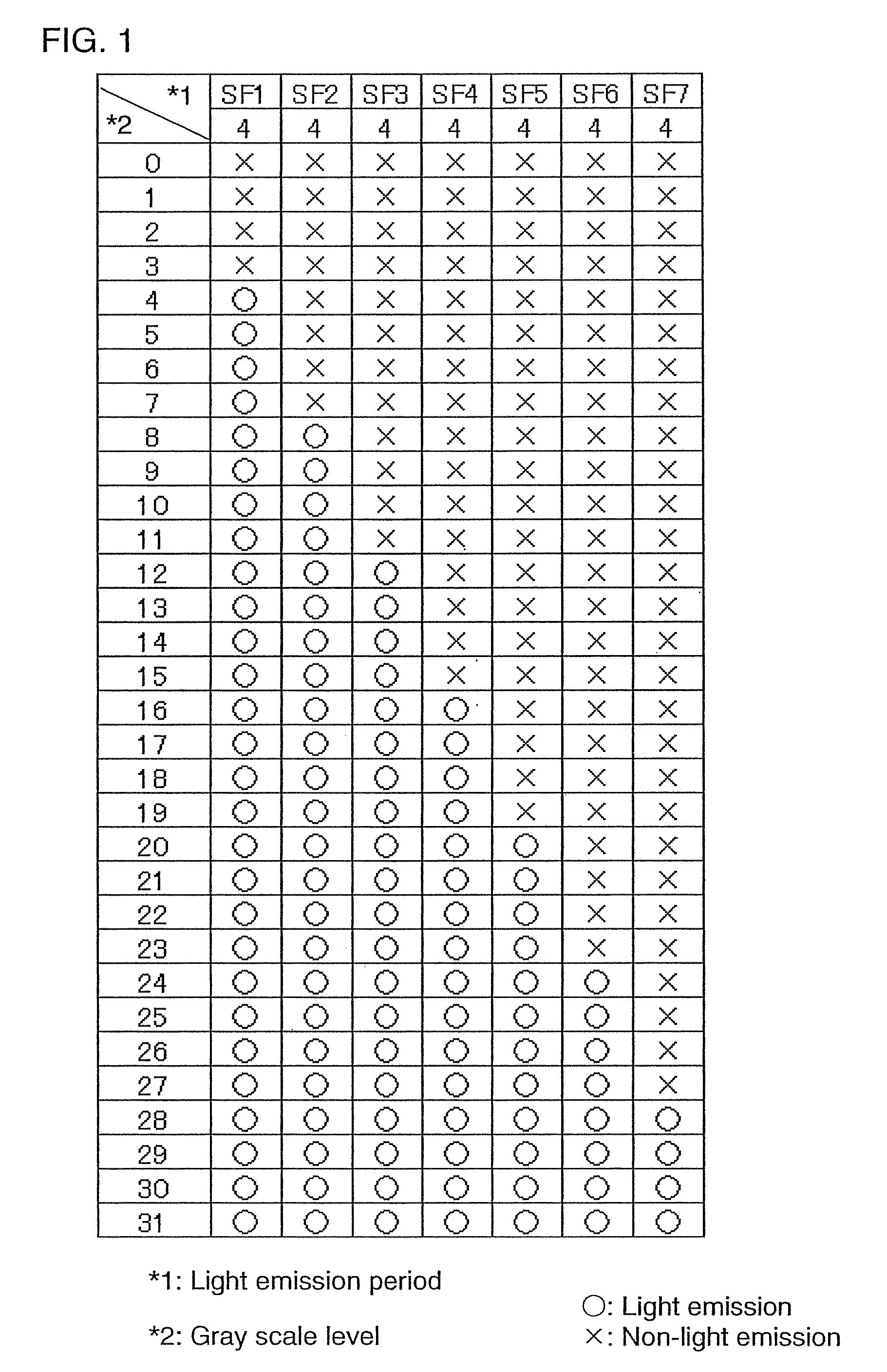
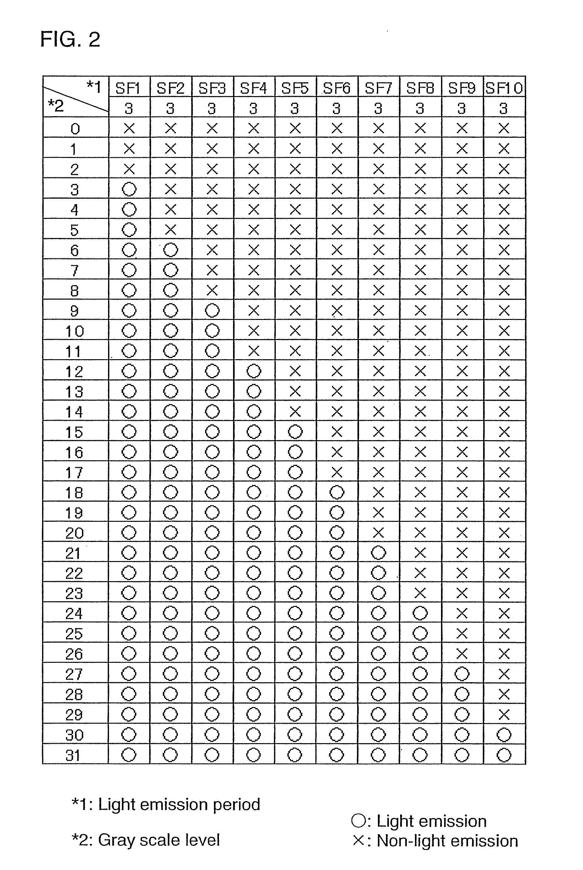
[0065]Here, for example, 5-bit gray scale is expressed. That is, description is made on the case of 32 gray scale levels.

[0066]According to the invention, gray scale is expressed by sequentially adding light emission period of each subframe (or the number of light emission in a certain time). That is, the higher the gray scale is, the light emitting element emits light in more subframes. Therefore, the subframe in a light emission state in the low gray scale level is also in light emission state in the high gray scale level. Such a gray scale method is referred to as a superimpose time gray scale method. By the superimpose time gray scale method, whole gray scale levels are expressed.

[0067]Next, description is made on a method for selecting a subframe in each gray scale level, that is, whether each subframe emits light or not in each gray scale level. FIG. 1 shows a method for selecting subframes in the case where one frame is formed of seven subframes. Accordingly, 3-bit, namely ei...

embodiment mode 2

[0115]Hereinafter described in this embodiment mode are configurations of a display device, a signal line driver circuit, a gate line driver circuit, and the like, and operations thereof.

[0116]A display device includes a pixel portion 1101, a gate line driver circuit 1102, and a signal line driver circuit 1110 as shown in FIG. 11. The gate line driver circuit 1102 sequentially outputs selection signals to the pixel portion 1101. The gate line driver circuit 1102 is formed of a shift register, a buffer circuit, and the like.

[0117]Besides, the gate line driver circuit 1102 often includes a level shifter circuit, a pulse width control circuit and the like. The shift register outputs pulses for sequential selection. The signal line driver circuit 1110 sequentially outputs video signals to the pixel portion 1101. The shift register 1103 outputs pulses for sequential selection. The pixel portion 1101 displays an image by controlling a state of light in accordance with the video signals. T...

embodiment mode 3

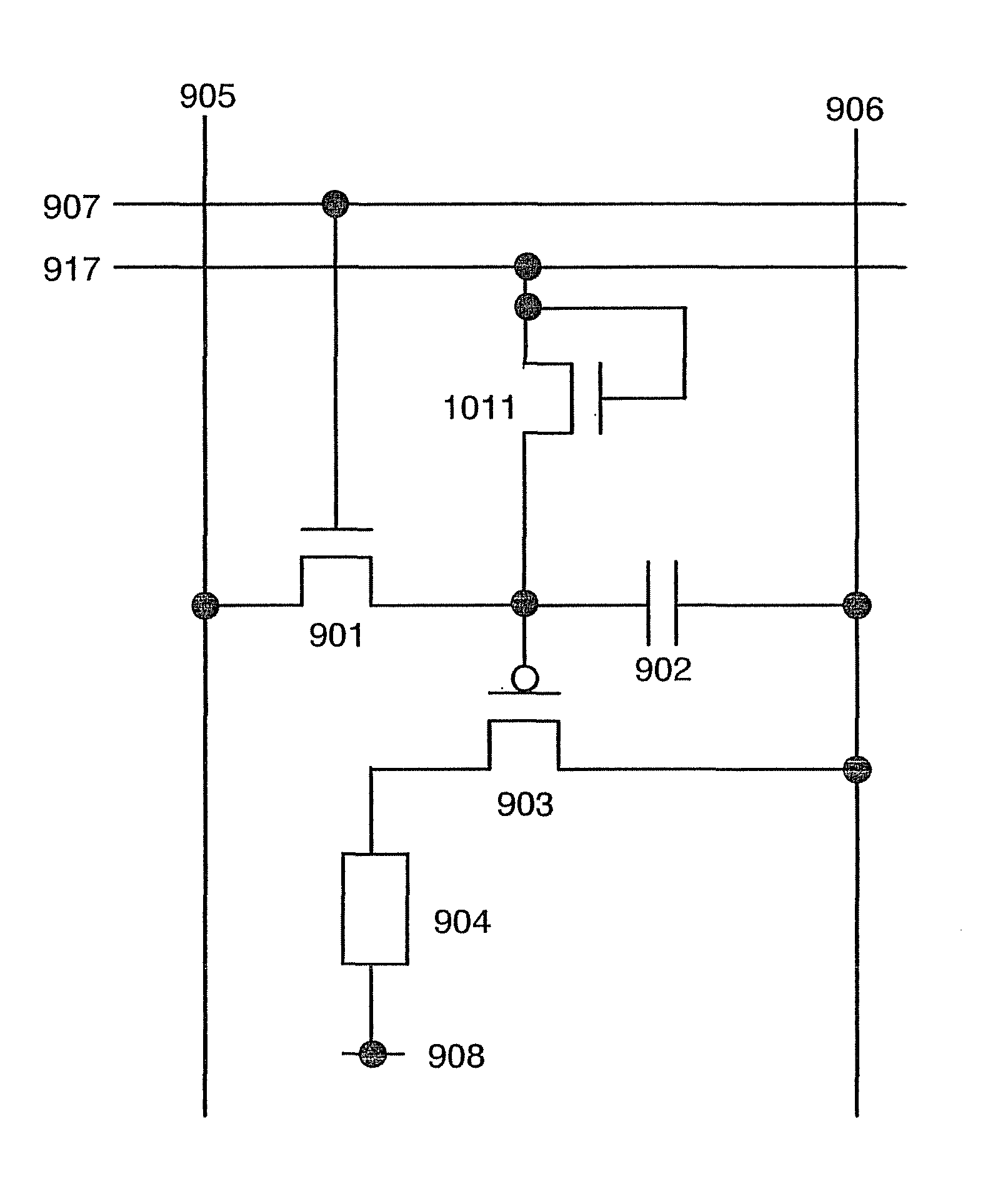
[0129]Next, description is made on a layout of a pixel of a display device of the invention. As an example, FIG. 13 shows a layout of the circuit diagram shown in FIG. 10. Similarly, FIG. 14 shows a layout of the circuit diagram shown in FIG. 9. It is to be noted that the circuit diagram and the layout are not limited to FIGS. 10, 9, 13, and 14.

[0130]First, FIG. 13 is referred. FIG. 13 includes a selecting transistor 1301, a driving transistor 1303, a diode-connected erasing transistor 1311, and an electrode 1304 of a display element. A source and a drain of the selecting transistor 1301 are connected to a signal line 1305 and a gate of the driving transistor 1303 respectively. A gate of the selecting transistor 1301 is connected to a first gate line 1307. A source and a drain of the driving transistor 1303 are connected to a power source line 1306 and the electrode 1304 respectively. The diode-connected erasing transistor 1311 is connected to the gate of the driving transistor 1303...


PUM


Abstract

In a display device in which one frame is divided into a plurality of subframes and a gray scale is expressed by a time gray scale method, there is a problem of pseudo contour. A gray scale is expressed by sequentially adding a weight of each subframe (light emission period, light emission time, and the like). Further, an erasing diode is provided in a pixel. By turning this erasing diode on, the signal stored in the pixel is erased, thereby a non-light emission period is provided. Accordingly, subframes with different light emission periods can be easily formed.

Description

[0001]This application is a continuation of pending application Ser. No. 11 / 328,319 filed on Jan. 9, 2006.BACKGROUND OF THE INVENTION[0002]1. Field of the Invention[0003]The present invention relates to a display device and a driving method thereof, and in particular to a display device which employs a time gray scale method.[0004]2. Description of the Related Art[0005]In recent years, a self-luminous display device having a pixel formed of light emitting elements such as a light emitting diode. As a light emitting element used for such a self-luminous display device, a light emitting diode (also referred to as an OLED (Organic Light Emitting Diode), an organic EL element, an inorganic EL element, and an electroluminescence (also referred to as an EL element) is attracting attentions and starting to be used for an EL display (an organic EL display, an inorganic EL display, or a display including an element containing organic and inorganic substances). A light emitting element such a...

Claims


Application Information

Patent Timeline
Patent Type & Authority Patents(United States)
IPC IPC(8): G09G3/30H05B44/00
CPCG09G3/3258G09G3/2025G09G3/2029G09G3/2044G09G3/2059G09G3/2074G09G2300/0842G09G2300/088G09G2320/0233G09G2320/0261G09G2320/0276
Inventor KIMURA, HAJIMEYAMAZAKI, SHUNPEI
Owner SEMICON ENERGY LAB CO LTD
Why Eureka
Try Eureka