
Vehicle periphery monitoring device

Inactive Publication Date: 2012-11-01
AISIN SEIKI KK
View PDF1 Cites 12 Cited by
  • Summary
  • Abstract
  • Description
  • Claims
  • Application Information

AI Technical Summary

Benefits of technology

[0006]The present invention was contrived in view of the foregoing problems, and an object thereof is to provide a vehicle periphery monitoring device wherein a switch can be made between a wide-angle display and an enlarged display, and an image obtained by capturing a view of the periphery of the vehicle can be displayed on an onboard display device, and wherein the mutual relationship between the pre- and post-switching images can be presented to a user with high visibility and a light computational load.
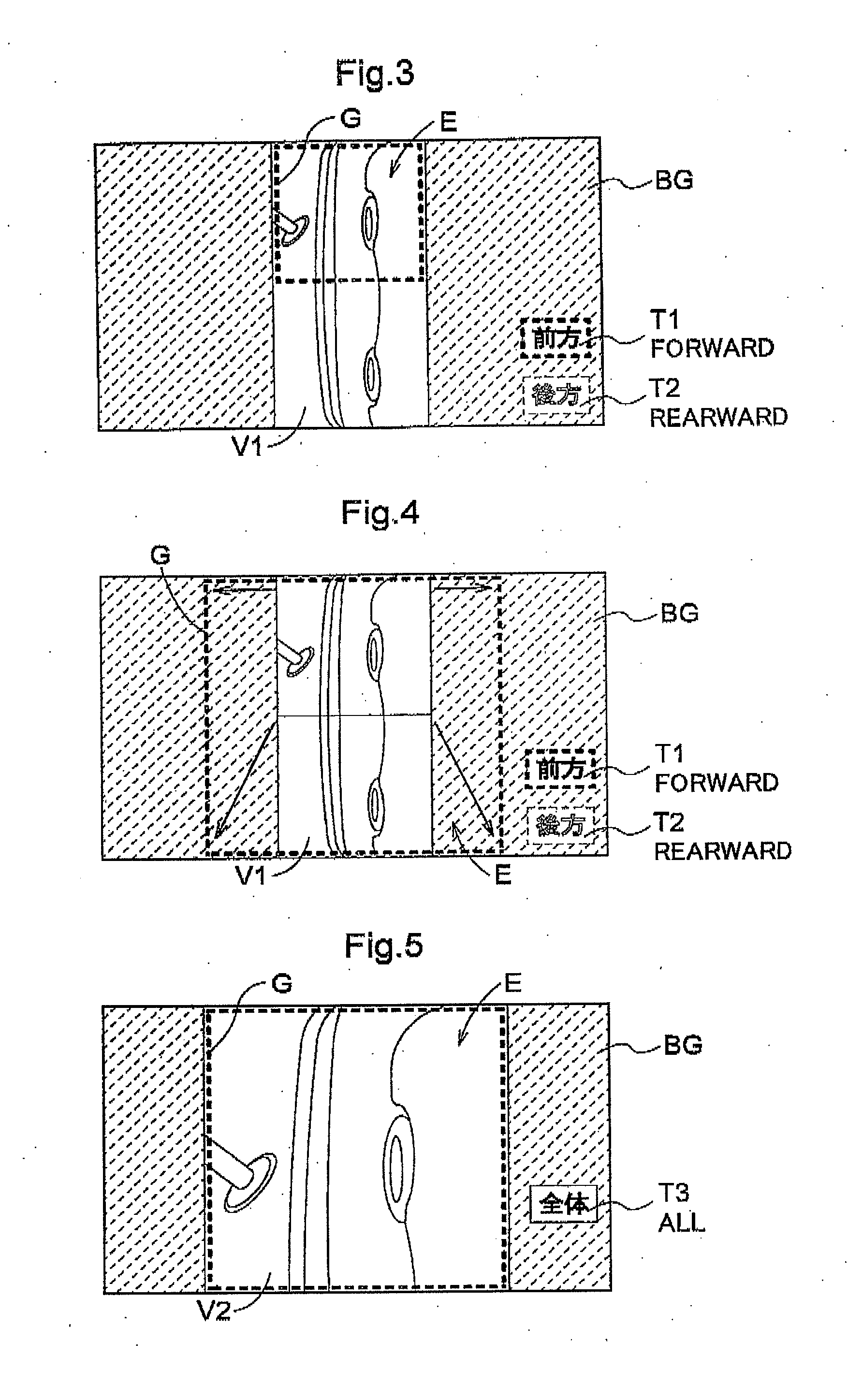
[0013]In this manner, the mutual relationship between the images before and after switching is displayed without breakup due to continuous variation in the highlighted region set on the screen. The computational load becomes very heavy when display data is switched while varying the magnification ratio of the enlarged display data in a stepwise fashion. However, in the case that the surface area of the highlighted region is continuously varied, the computational load is dramatically reduced because display can be carried out without regard for the captured wide-angle imaging data.
[0014]As a result, a vehicle periphery monitoring device can be provided in which a captured image of the peripheral view of the vehicle can be switched between a wide-angle display and an enlarged display, and displayed on an onboard display device, and the mutual relationship between the images before and after switching can be presented to the user with high visibility and a light computational load.
[0016]In accordance with this aspect, two-types of control are sufficient before and after the display of data: display of pre-switching display data and display of post-switching display data. The highlighting display showing the target region is carried out with a light computational load independent of displaying the display data. Since the pre-switching display data is displayed immediately prior to switching, the mutual relationship between the images before and after switching can be more readily ascertained.
[0018]Such a frame can be superimposed on the display data with a light computational load. Visibility is good because the target region is directly enclosed by the frame. Therefore, it is possible to provide a vehicle periphery monitoring device that can present the mutual relationship between the pre- and post-switching images to a user with high visibility and a light computational load.
[0020]The surface area of the background on the screen of the display device is varied, making it is possible to display the clipped display data of the target region and to obtain a visibility effect in which the display data to be displayed is magnified or reduced in size. The computational load is light because such modifications to the surface area of the background do not involve any image processing of the display data. Therefore, it is possible to provide a vehicle periphery monitoring device that can present the mutual relationship between the pre- and post-switching images to a user with high visibility and a light computational load.

Problems solved by technology

In other words, with the drive assistance device disclosed in Patent Document 1, it is difficult for the occupant to know which location in the imaging range of the camera is being enlarged.
For example, the correspondence between the images before and after switching may be particularly difficult to understand when a certain location is clipped, enlarged, and displayed from a wide-angle display.
In the case that a switch is made from an enlarged display to a wide-angle display, it may be difficult to understand where the enlarged location is positioned in the corresponding wide-angle display.

Method used


Image

  • Vehicle periphery monitoring device
  • Vehicle periphery monitoring device
  • Vehicle periphery monitoring device

Examples


first embodiment

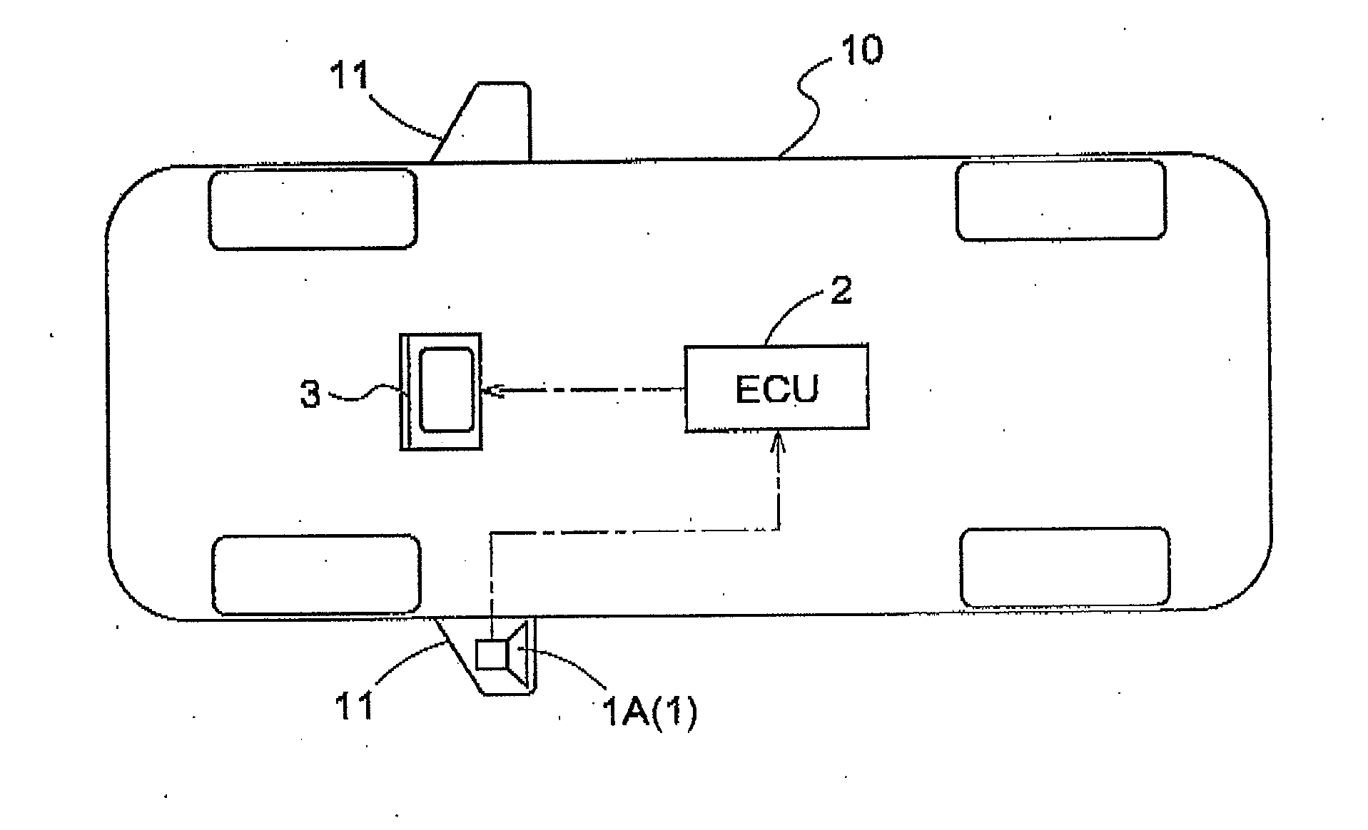
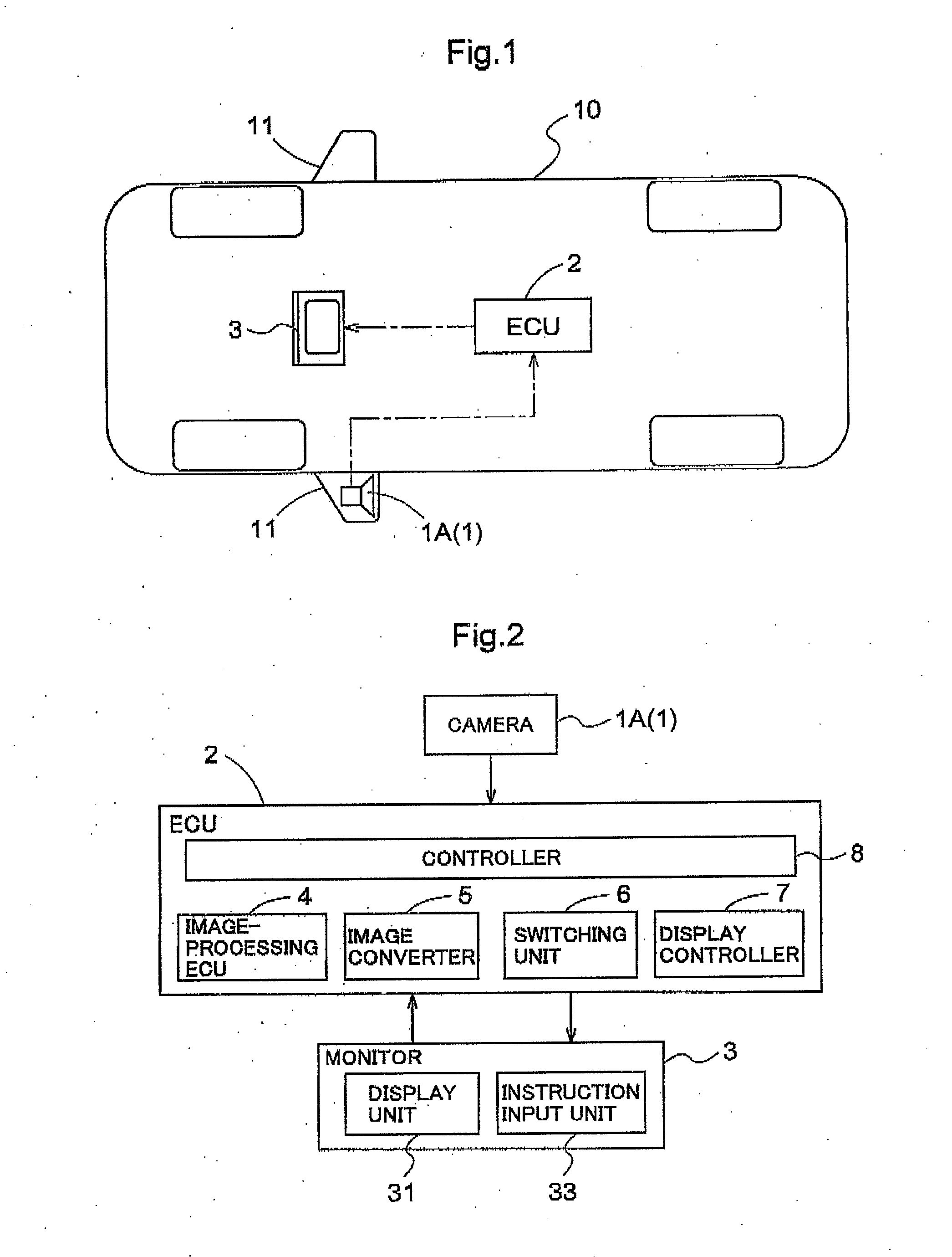
[0038]An embodiment of a vehicle periphery monitoring device (hereinbelow referred to simply as a “periphery monitoring device”) of the present invention will be described below with reference to the accompanying drawings. FIG. 1 is a schematic block diagram showing a configuration example of a vehicle 10 on which the periphery monitoring device of the present invention is mounted. FIG. 2 is a schematic block diagram showing a configuration example of a vehicle periphery monitoring device of the present invention.

[0039]The main part of the periphery monitoring device of the present invention is an ECU 2. The ECU 2 is provided with a microprocessor for processing information, e.g., image information, that has been entered, and a digital signal processor (DSP). The ECU 2 is composed of an electronic circuit in which the processor is a main component. The ECU 2 has a storage unit that is housed in the processor or is composed of a memory, register, or the like mounted as a separate com...

second embodiment

[0061]In the example described above, an example was described for a case in which an image based on the wide-angle imaging data captured by a single camera 1 (1A) mounted on the vehicle 10 is displayed on the monitor 3. However, the present invention is not limited to a single camera 1, and the present invention can also be applied to a case in which images based on wide-angle imaging data captured by a plurality of cameras 1 are displayed on the monitor 3. A second embodiment of the present invention is described below with reference to FIGS. 12 to 17. FIG. 12 is a schematic block diagram showing another example of the configuration of the vehicle 10 in which the periphery monitoring device of the present invention has been mounted. FIG. 13 is a schematic block diagram showing another example of the configuration of the periphery monitoring device of the present invention.

[0062]In the present embodiment, two cameras 1 are provided as imaging devices for capturing an image of a veh...


PUM


Abstract

Wide-angle imaging data obtained by capturing a view of a vehicle periphery can be converted into wide-angle display data for displaying the view in the same field of view on a display device, and into enlarged display data for enlarging and displaying a portion of the wide-angle imaging data. When the image on the screen of the display is switched between wide-angle display and enlarged display, the target region corresponding to the post-switching display data is set, highlighted, and displayed as the highlighted region (E) on the screen on the pre-switching display data (V1). The surface area of the highlighted region (E) is varied until the surface area highlighted region (E) is the same as the surface area of the target region on the post-switching display data. Lastly, the post-switching display data is displayed in the highlighted region (E).

Description

TECHNICAL FIELD[0001]The present invention relates to a vehicle periphery monitoring device for displaying a view of the periphery of the vehicle on an onboard display device on the basis of image data captured by an imaging device mounted on the vehicle.BACKGROUND ART[0002]There has been growing awareness of maintaining safety during vehicle operation in recent years, and various techniques for improving safety have been devised and implemented by assisting the driver in operating the vehicle or the like. For example, a drive assistance device has been implemented in which locations that are difficult for the occupant to see are captured by a camera mounted on the vehicle and displayed on a monitor device in the passenger compartment. Patent Document 1, i.e., Japanese Laid-open Patent Application No. 2004-194071, discloses a drive assistance device in which image data acquired by a camera mounted on a side mirror of the vehicle is displayed on a monitor device in the passenger comp...

Claims


Application Information

Patent Timeline
IPC IPC(8): H04N7/18H04N7/00
CPCB60R2300/102B60R2300/70B60R2300/8026H04N7/181G06T3/047B60R1/28B60R1/25H04N7/18
Inventor KUBOYAMA, TSUYOSHIWATANABE, KAZUYAYAMANAKA, TAKASHIYAMANAKA, YUMI
Owner AISIN SEIKI KK
Learn More