Image splicing method and apparatus

a splicing method and image technology, applied in the field of image processing technologies, can solve problems such as serious distortion of the constructed seamless wide-angle imag

Inactive Publication Date: 2012-11-01
HUAWEI DEVICE CO LTD
View PDF8 Cites 73 Cited by
  • Summary
  • Abstract
  • Description
  • Claims
  • Application Information

AI Technical Summary

Benefits of technology

[0022]The homography matrix may be directly calculated through the spatial relationship parameter between two scenes, the spatial relationship parameter between the cameras, and the internal parameters of the cameras. In this way, no overlapped area between images is required when the homography matrix is calculated, that is to say, in the embodiments of the present invention, the homography matrix is calculated in the case of no overlapped area between two images or only one column of overlapped pixels between two images, and the image splicing is accomplished by using the homography matrix.

Problems solved by technology

However, these hardware devices capture as much information as possible on a limited imaging surface, which causes serious distortion of the constructed seamless wide-angle image.

Method used


Image

  • Image splicing method and apparatus
  • Image splicing method and apparatus
  • Image splicing method and apparatus

Examples


embodiment 1

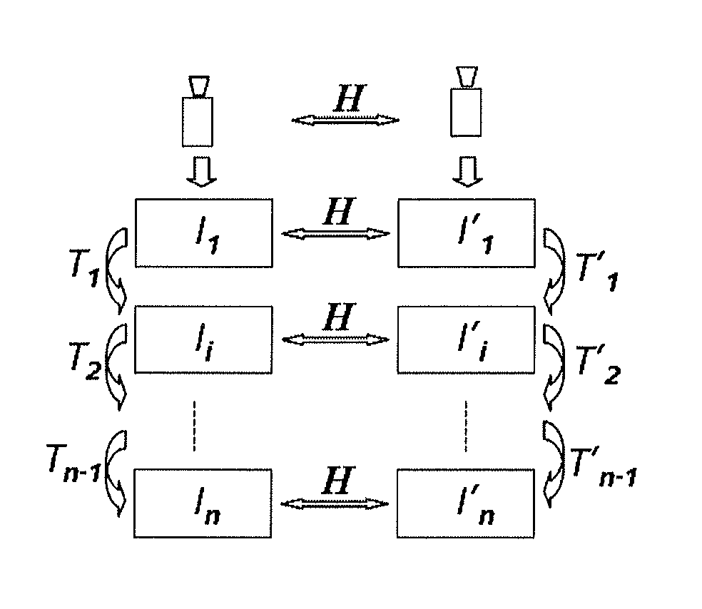
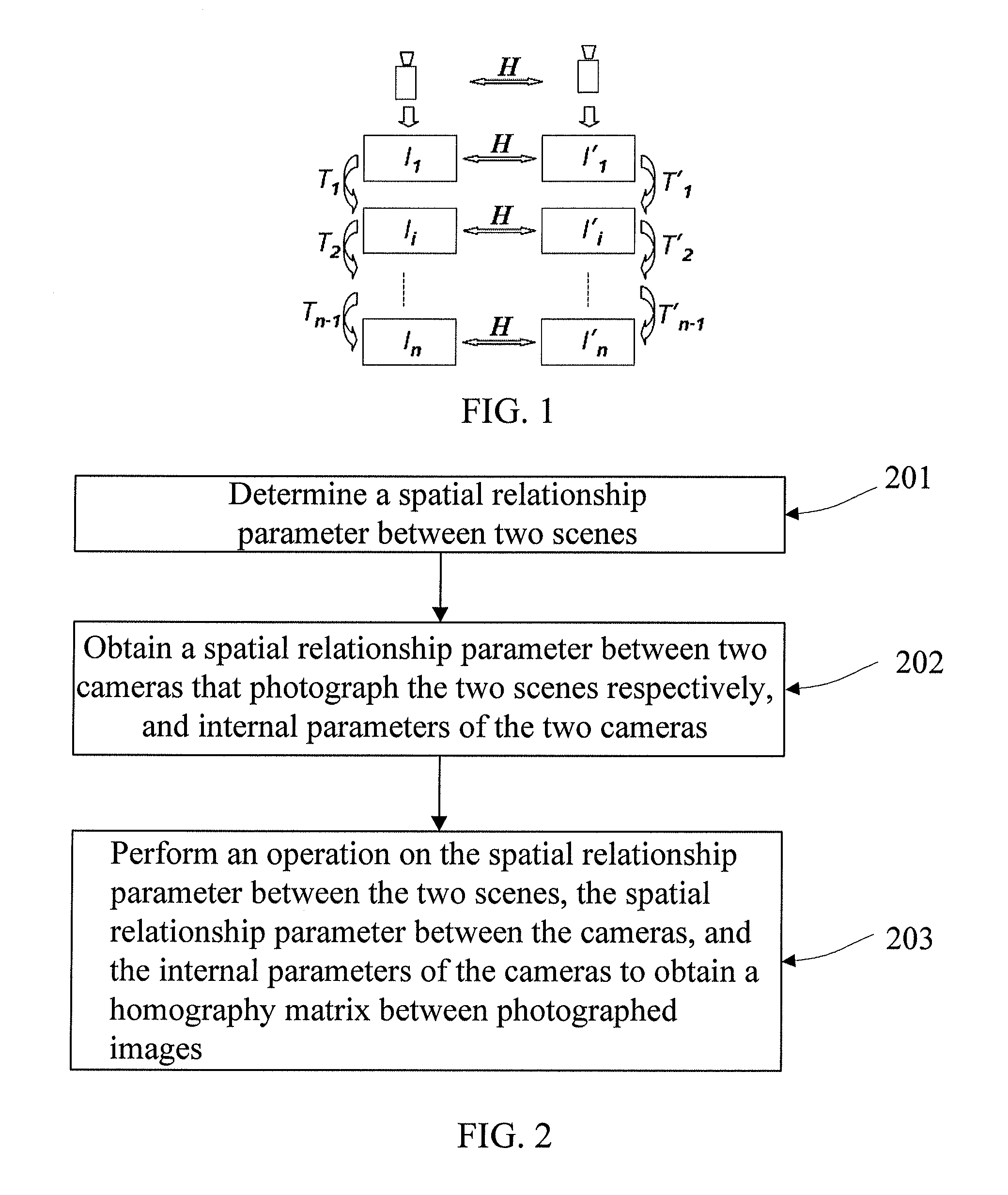
[0047]If two cameras photograph two scenes respectively to obtain images of the two scenes, or one camera photographs two scenes separately to obtain images of the two scenes, in order to splice the obtained images of the two scenes together, a homography matrix between two images needs to be calculated. A first embodiment of the present invention provides a method for calculating a homography matrix between cameras. As shown in FIG. 2, the method includes:

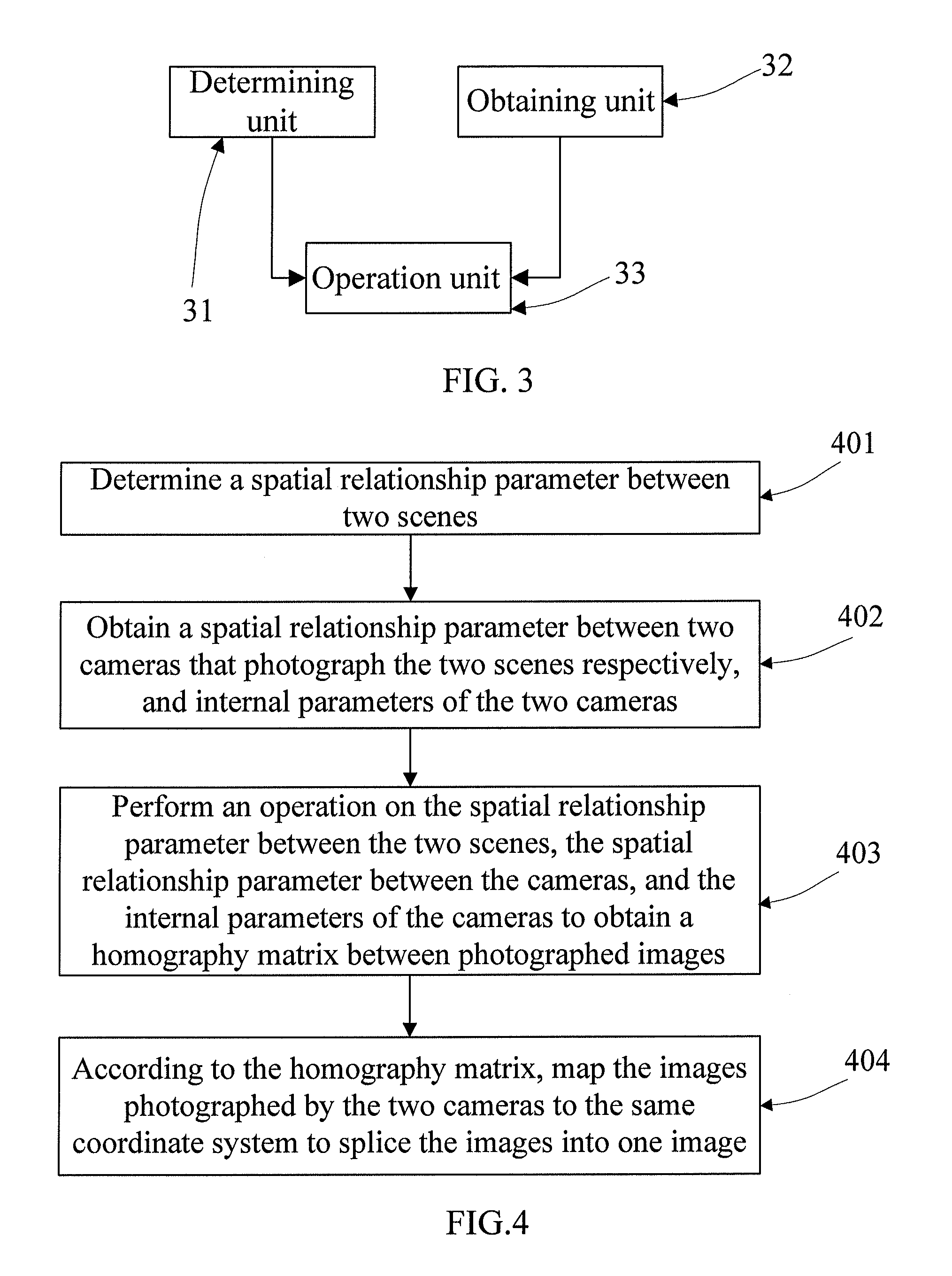
[0048]201: Determine a spatial relationship parameter between two scenes. The spatial relationship parameter may be represented by a function. It is assumed that one scene is P1 and the other scene is P2, and then the spatial relationship parameter may be represented by P2=f(P1).

[0049]202: Obtain a spatial relationship parameter between two cameras that photograph the two scenes respectively, and internal parameters of the two cameras. The spatial relationship parameter may also referred to as an external parameter and is used to ...

embodiment 2

[0067]Application of this embodiment of the present invention is described in the following by taking a photographed image of a large checkerboard as an example. First, a large checkerboard as shown in FIG. 6 is made. There are two areas that are to be photographed and are enclosed by a line 1 and a line 2 in the large checkerboard. Sizes of these two areas to be photographed may be adjusted according to an actual requirement. A black check or a white check in the foregoing checkerboard is generally a square or a rectangle with a known size. Sizes of checks in the checkerboard are known, and therefore, a position relationship (that is, a spatial relationship parameter between two scenes) of a three-dimensional space of the two areas to be photographed may be known or calculated out. That is to say, choosing any pair of checks in an area to be photographed, a relative position relationship between them is known or may be calculated out.

[0068]In addition, a left camera and a right cam...

embodiment 3

[0091]In this embodiment, it is assumed that P1 and P2 are two points in two scenes, and a spatial position relationship between the two scenes is P2=f (P)=P1+b. And it is assumed that K, K′ a re internal parameter matrixes of a left camera and a right camera respectively, [R1 t1], [R2 t2] are external parameters (which may together represent a spatial relationship between cameras) of the left camera and the right camera respectively, and [R t] a re a rotation matrix and a translation vector of the right camera relative to the left camera.

[0092]It is assumed that coordinates of P1 and P2 are p1 and p2 in their respective corresponding images, and P1 and P2 correspond to points and Pc1 and Pc2 in a camera coordinate system, then:

{ P1=R1Pc1+t1P2=R2Pc2+t2

[0093]A relative position relationship between cameras does not change, and therefore, H does not change either,

[0094]then: P2=R2Pc2+t2=R1Pc1+t1+b, accordingly, R2s2Pc2+t2=R1s1Pc1+t1+b , where s1 and s2 represent depths of Pc1 and Pc2....


PUM


Abstract

The present invention discloses an image splicing method and apparatus, and relates to the field of image processing technologies. In embodiments of the present invention, first, a spatial relationship parameter between two scenes is determined; a spatial relationship parameter between two cameras that photograph the two scenes respectively, and internal parameters of the two cameras are obtained; and then, an operation is performed on the spatial relationship parameter between the two scenes, the spatial relationship parameter between the cameras, and the internal parameters of the cameras to obtain a homography matrix between photographed images; and according to the homography matrix, the images photographed by the two cameras are mapped to the same coordinate system to splice the images into one image. The embodiments of the present invention are mainly applied to calculation of a homography matrix between two images, especially to calculation of a homography matrix in image splicing process.

Description

CROSS-REFERENCE TO RELATED APPLICATIONS[0001]This application is a continuation of International. Application No. PCT / CN2010 / 080053, filed on Dec 21, 2010, which claims priority to Chinese Patent Application No. 200910247061.7, filed on Dec. 21, 2009, both of which are hereby incorporated by reference in their entireties.FIELD OF THE INVENTION[0002]The present invention relates to the field of image processing technologies, and in particular, to an image splicing method and apparatus.BACKGROUND OF THE INVENTION[0003]A seamless wide-angle image can be directly constructed through hardware devices such as a reflection / refraction system and a fisheye lens. However, these hardware devices capture as much information as possible on a limited imaging surface, which causes serious distortion of the constructed seamless wide-angle image.[0004]An image in a digital format may be photographed through a digital imaging device, and a digital panoramic image with a wider field of view may be obt...

Claims


Application Information

Patent Timeline
Patent Type & Authority Applications(United States)
IPC IPC(8): H04N5/228H04N13/02
CPCG06T7/002H04N5/2624G06T2207/10012G06T3/0068G06T2207/20032G06T2207/20221G06T2207/10024G06T7/85
Inventor LI, KAI
Owner HUAWEI DEVICE CO LTD
Why Eureka
Try Eureka