Modular rotational electric actuator

a technology of electric actuators and modules, applied in mechanical equipment, manufacturing tools, gearing, etc., can solve the problems of increasing the weight of the system, and affecting the operation of the system

Active Publication Date: 2012-11-15
HDT EXPEDITIONARY SYST
View PDF9 Cites 83 Cited by
  • Summary
  • Abstract
  • Description
  • Claims
  • Application Information

AI Technical Summary

Benefits of technology

[0007]In some illustrative embodiments disclosed as illustrative examples herein, a modular rotational electric actuator includes an output housing including a front housing portion and a rear housing portion. The output housing includes internal drive components that are operatively located within the output housing. Additionally, the output housing includes control electronics that are integrated within the output housing, and which are in communication with the internal drive components. The control electronics include at least one sensor that is operatively coupled to at least one of the internal drive components, which provides at least one signal or value to the control electronics indicating a position, a torque, a load, or a speed associated with the actuator.

Problems solved by technology

Prior art prosthetic robotic arms cannot produce torque, strength, or lift capability comparable to a human arm within the dimensions and weight of the average human arm.
The electromechanical devices which drive the prior art robotic limbs are bulky, heavy, and inefficient.
Moreover, these prior art limbs require generous power sources which typically involves the use of numerous batteries or bulky external power supplies thereby further adding to the weight of the system.
Such increased weight limits the portability and ergonomics of a prosthetic or robotic limb.
Such solutions are disadvantageous because they only work for a specific joint.
In other words, they are not usable for joints between multiple arm modules.
Although prosthetic technology has advanced in recent years, the prior art still has failed to bridge the gap between manmade prosthetics and user demands and needs.
Robotic arms used as prostheses are not fully articulated to give the user the same degrees of freedom as a natural arm, not to mention the speed and torque of a human arm.
Moreover, the human arm can sense pressure, which conventional man-made arms cannot do.

Method used


Image

  • Modular rotational electric actuator
  • Modular rotational electric actuator
  • Modular rotational electric actuator

Examples


Embodiment Construction

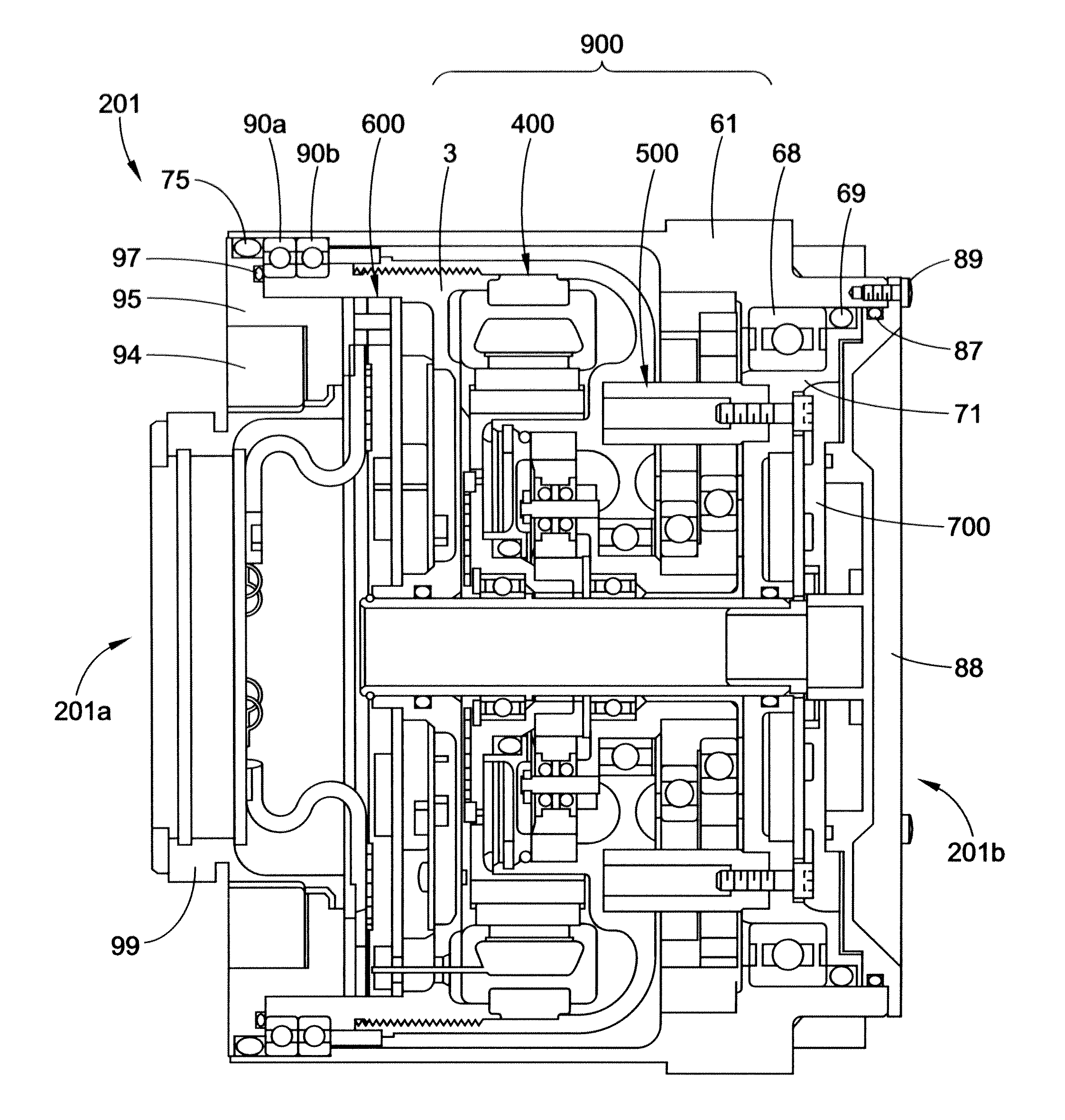
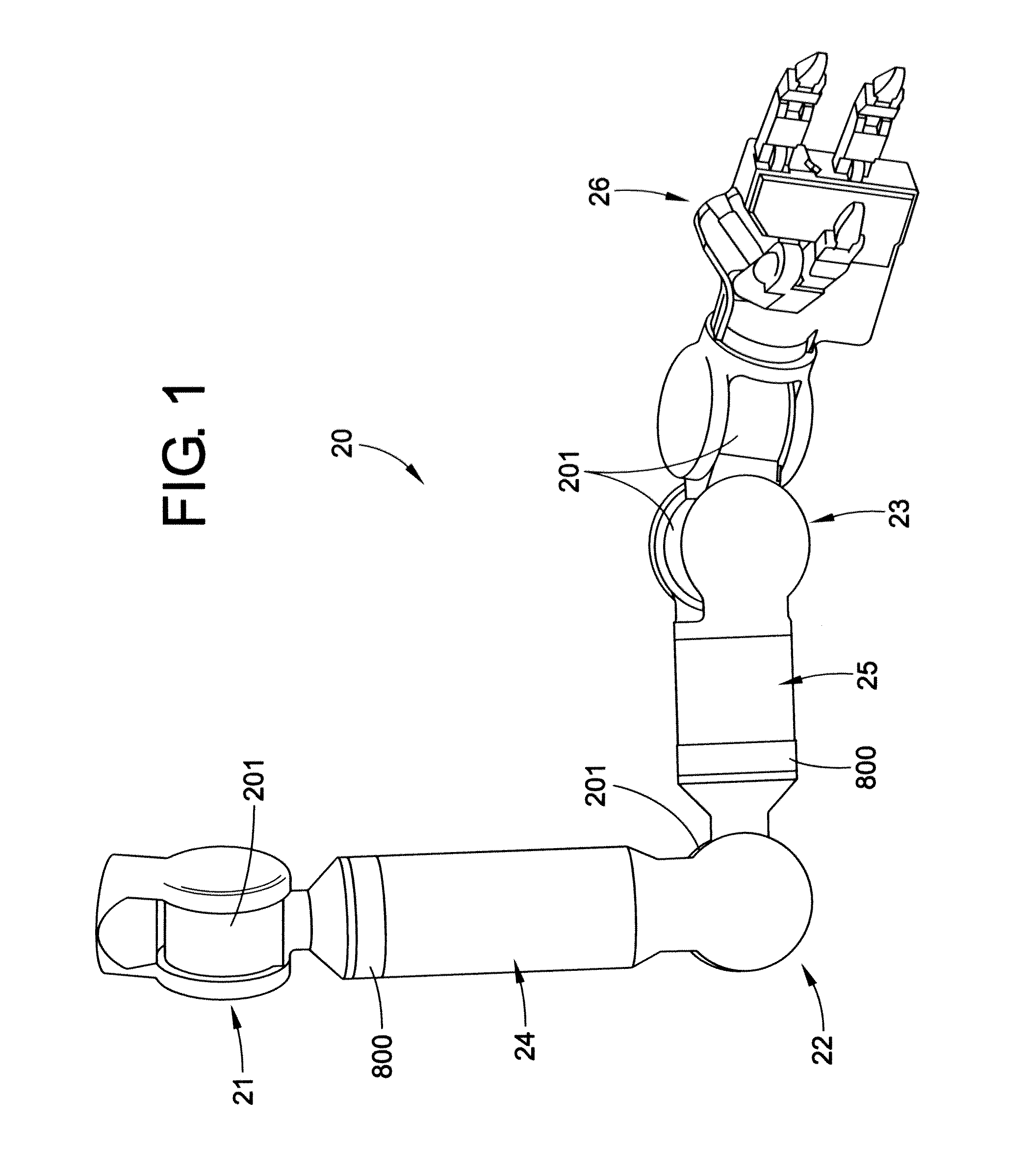
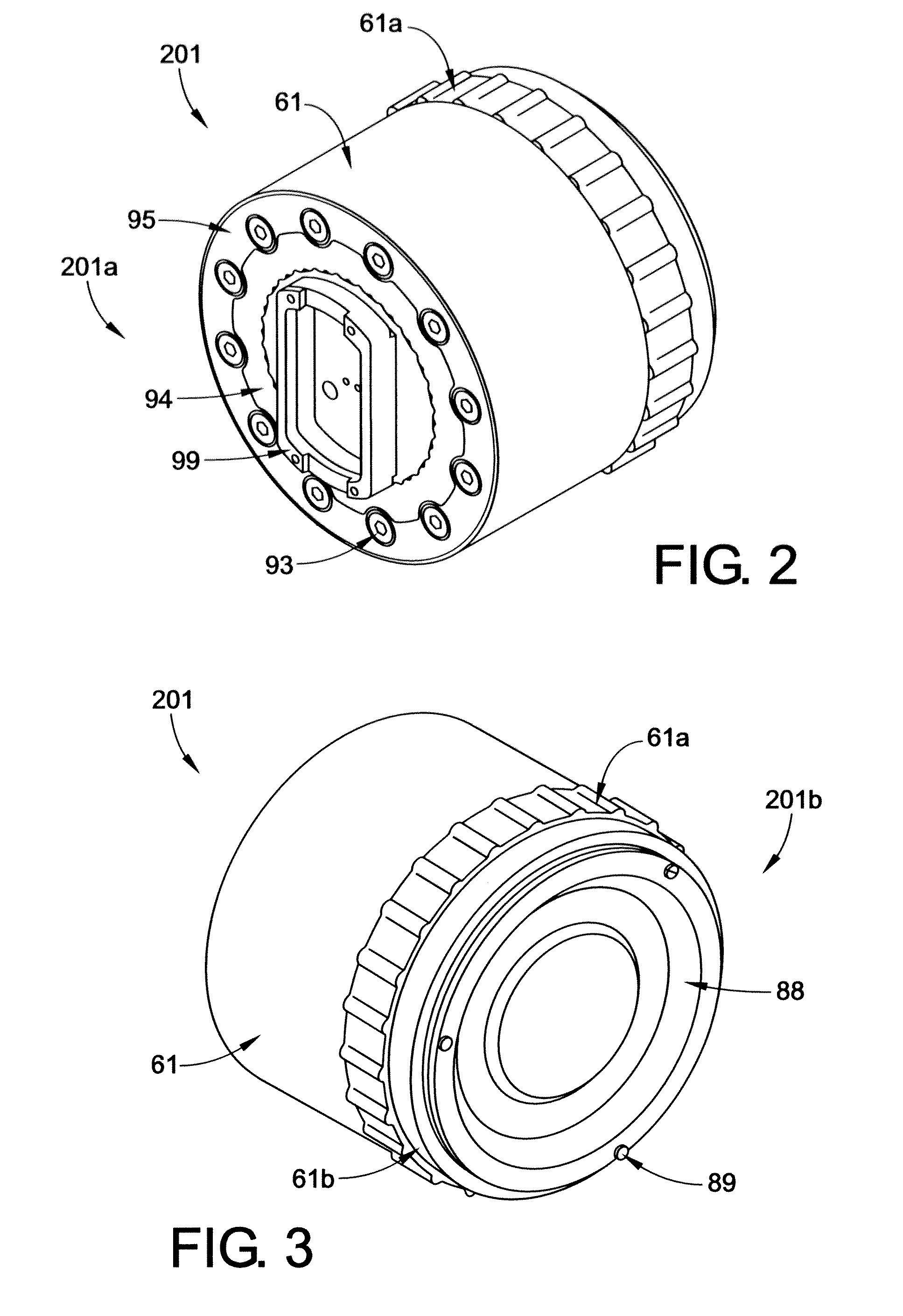
[0037]With reference to FIG. 1, an artificial or robotic limb 20 is shown, according to one embodiment of the present disclosure. By way of example, the robotic limb 20 may comprise an arm that includes a number of rotatable joints, such as a shoulder joint 21, an elbow joint 22, and / or a wrist joint 23. In addition, the robotic limb 20 may include one or more rotatable limb or arm segments 24, 25. A series of electromechanical robotic limb modular rotational electric actuators can be incorporated into either or both of the joints or limb segments for the purpose of moving a manipulator 26 or other object (e.g., tool, surgical device, weapon, etc.) in a prescribed manner necessary to perform a particular task or operation. A first embodiment of a modular rotational electric actuator 201 (also referenced herein as an actuator) is particularly adapted to be used at radial joint locations (such as the shoulder 21, elbow 22, and / or wrist 23). By comparison, a second embodiment of a modu...


PUM


Abstract

A modular rotational electric actuator includes an output housing and internal drive components that include integrated control electronics, a torque sensor, and a portion of a joint assembly. The joint assembly includes a joint connector coupled to the internal drive components, including integrated control electronics, e.g., by a resilient member. The resilient member elastically couples the joint connector to a portion of the output housing, the joint connector including a portion that extends outward therefrom.

Description

CROSS-REFERENCE TO RELATED APPLICATIONS[0001]This application claims priority to and the benefit of U.S. Provisional Patent Application Ser. No. 61 / 485,848, filed May 13, 2011, entitled ROBOTIC LIMB DRIVE, the entirety of which is hereby incorporated by reference.BACKGROUND[0002]The present disclosure relates generally to rotational electric actuators. More particularly, it relates to modular actuators for manmade or artificial limbs for robotic prosthetic or orthotic devices, and the like.[0003]Prior art prosthetic robotic arms cannot produce torque, strength, or lift capability comparable to a human arm within the dimensions and weight of the average human arm. Stated differently, prosthetic robotic arms simply do not have the same power density as does a human arm. The electromechanical devices which drive the prior art robotic limbs are bulky, heavy, and inefficient. Moreover, these prior art limbs require generous power sources which typically involves the use of numerous batte...

Claims


Application Information

Patent Timeline
Patent Type & Authority Applications(United States)
IPC IPC(8): H02K11/00
CPCB25J9/08B25J9/102F16H1/32H02K5/225H02K7/003H02K7/116H02K11/0042H02K21/16H02K29/08H02K2213/12F16H1/46H02K11/0047H02K7/14H02K11/24H02K11/25
Inventor JOHNSON, EZRAVAN DOREN, THOMAS W.LONTZ, W. TRAVISCOLEMAN, BILLY MITCHELL
Owner HDT EXPEDITIONARY SYST
Why Eureka
Try Eureka