Tubular coupling device

a tubular coupling and coupling technology, applied in the direction of drilling casings, drilling pipes, borehole/well accessories, etc., can solve the problems of incomplete make up, inadequate amount of make up torque to be applied to the connection, and components or tubular strings attached to become stuck in the wellbor

Inactive Publication Date: 2012-11-29
WEATHERFORD TECH HLDG LLC
View PDF10 Cites 54 Cited by
  • Summary
  • Abstract
  • Description
  • Claims
  • Application Information

AI Technical Summary

Benefits of technology

[0024]In one or more of the embodiments described herein, the method in

Problems solved by technology

As wellbore components are delivered and removed from a wellbore, the components or the tubular string they are attached to may become stuck in the wellbore.
If the distance to the downhole component is large, torsional deflection of the drill

Method used


Image

  • Tubular coupling device
  • Tubular coupling device
  • Tubular coupling device

Examples


Embodiment Construction

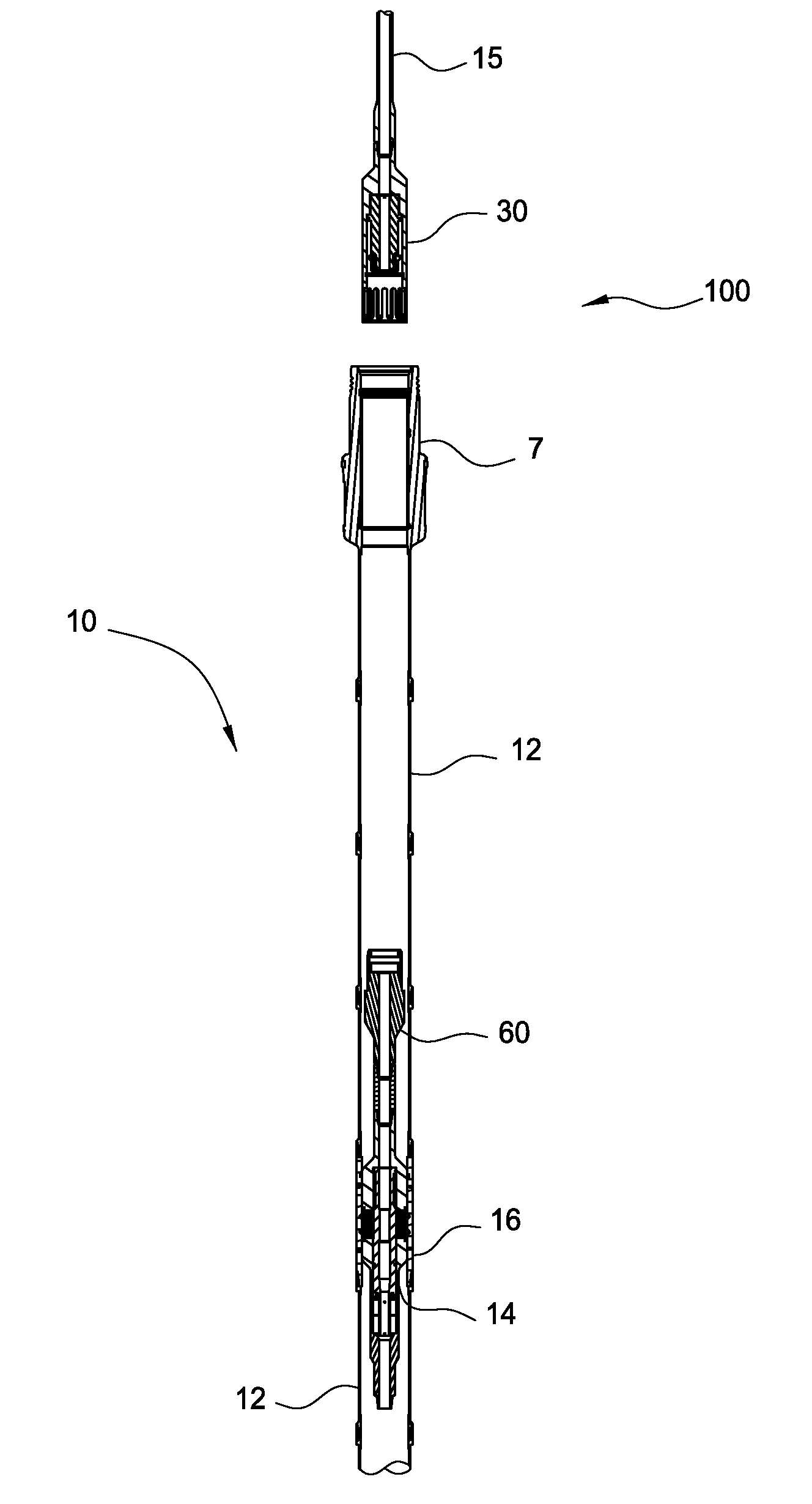
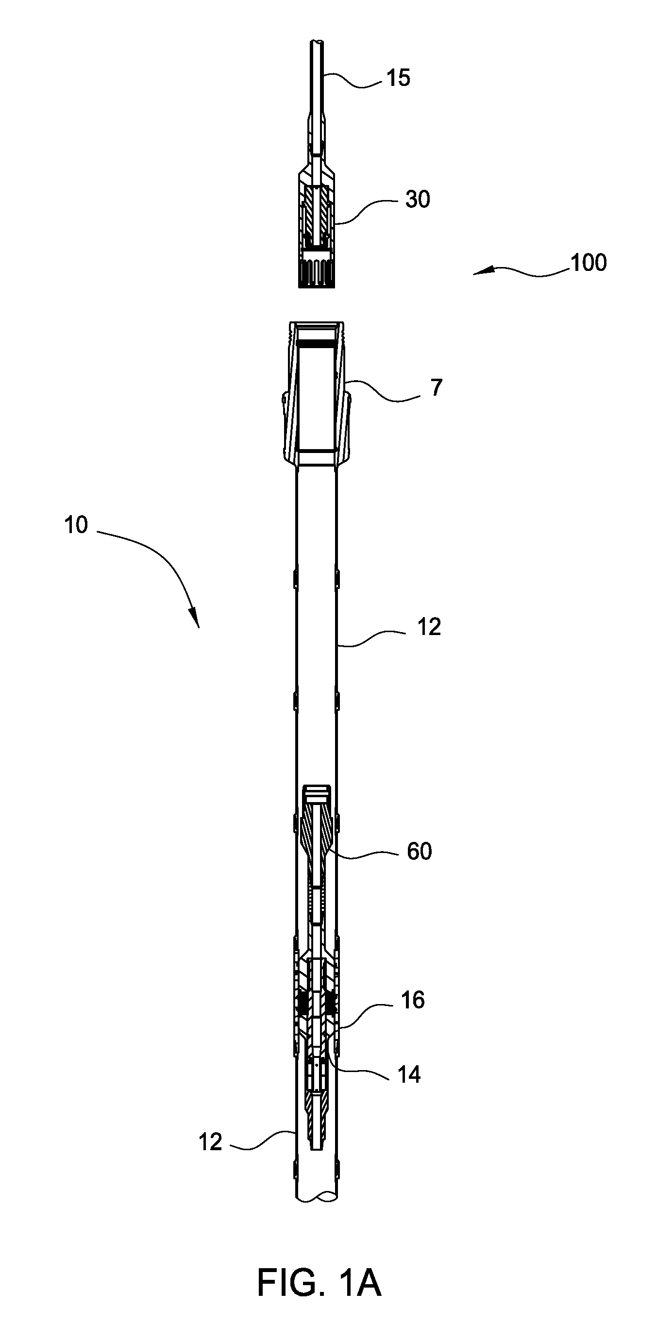
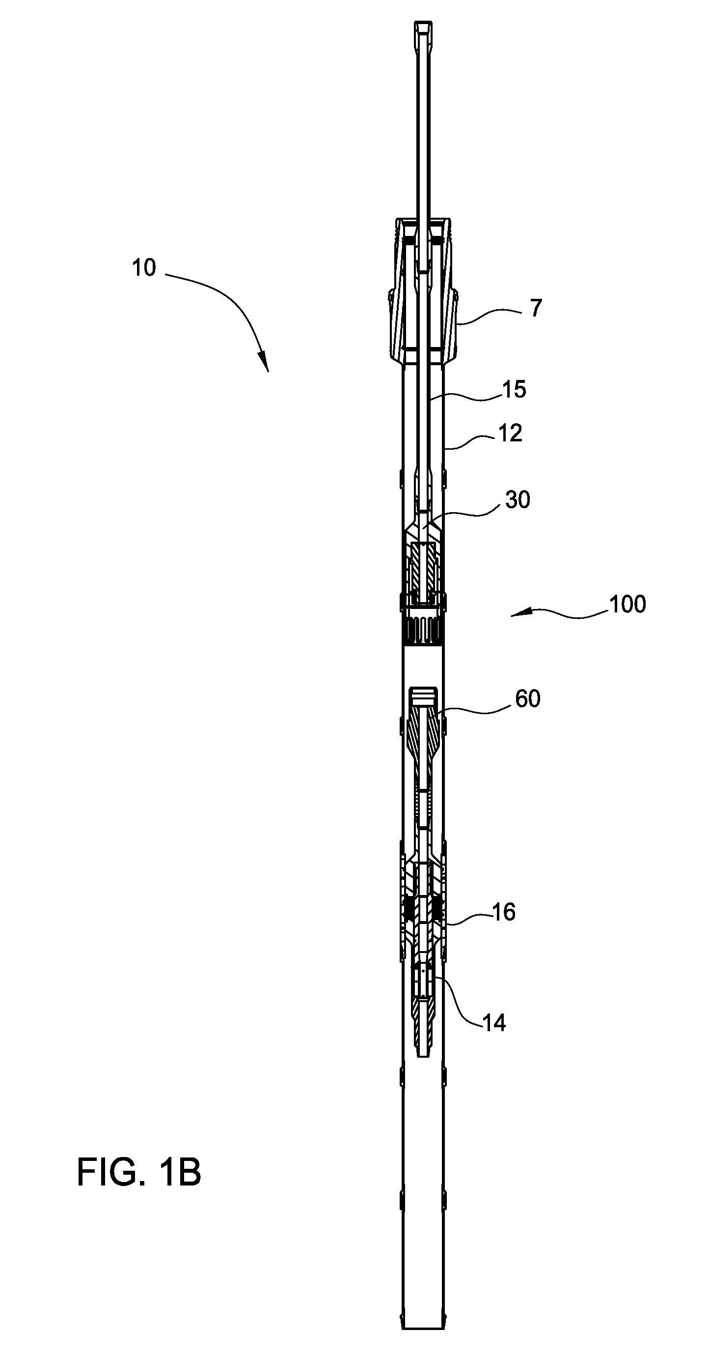
[0048]In one embodiment, a coupling device includes an upper adapter and a lower adapter. The lower adapter may be pre-installed on a downhole tool and positioned in a wellbore. The upper adapter may be attached to a conveyance and lowered into the wellbore for connection with the lower adapter. The upper adapter may be coupled to the lower adapter by sliding over the lower adapter and applying weight to actuate a locking mechanism. After coupling, axial and torque loads may be transmitted from the conveyance to the downhole tool.

[0049]FIG. 1A is a schematic view of an embodiment of a coupling device 100 used with a drilling system 10. The drilling system 10 includes a casing string 12, which may have a drill bit at a lower end thereof. A running tool 14 is attached to an interior of the casing string 12 for coupling to a conveyance such as a drillstring 15. The running tool 14 may be attached to the casing string 12 using a casing adapter 16. A suitable running tool is disclosed in...


PUM


Abstract

A coupling device includes an upper adapter and a lower adapter. The lower adapter may be pre-installed on a downhole tool and positioned in a wellbore. The upper adapter may be attached to a conveyance and lowered into the wellbore for connection with the lower adapter. The upper adapter may be coupled to the lower adapter by sliding over the lower adapter and applying weight to actuate a locking mechanism. After coupling, axial and torque load may be transmitted from the conveyance to the downhole tool.

Description

CROSS-REFERENCE TO RELATED APPLICATIONS[0001]This application claims benefit of U.S. Provisional Patent Application No. 61 / 490,033, filed May 25, 2011, which application is incorporated herein by reference in its entirety.BACKGROUND OF THE INVENTION[0002]1. Field of the Invention[0003]Embodiments of the invention generally relate to a tubular coupling device. Particularly, embodiments of the invention relate to a tubular coupling device for transmitting axial and torque loads.[0004]2. Description of the Related Art[0005]In the drilling, completion, and operation of a hydrocarbon well, various wellbore components are inserted and removed from a wellbore on a lower end of a conveyance such as a tubular string. Exemplary wellbore components include packers (to seal off production zones), motors, pumps, sensors, sliding sleeves (to control flow of fluid in and out of production tubing), hydraulically set liners (for lining during cementing of casing), whipstocks (to divert drill bit whi...

Claims


Application Information

Patent Timeline
IPC IPC(8): E21B23/00E21B17/02
CPCE21B17/02E21B31/20E21B17/046
Inventor TWARDOWSKI, ERIC M.
Owner WEATHERFORD TECH HLDG LLC
Why Eureka
Try Eureka