
Sectional rack

a sectional rack and rack technology, applied in the field of sectional racks, can solve the problems of low structural strength of the above-structured sectional rack, affecting the overall structure of the rack, and unable to balance the front and rear structural strength, so as to achieve the effect of increasing the overall structural strength

Inactive Publication Date: 2012-11-29
PROTREND ENTERPRISE CO LTD
View PDF0 Cites 5 Cited by
  • Summary
  • Abstract
  • Description
  • Claims
  • Application Information

AI Technical Summary

Benefits of technology

[0006]A primary object of the present invention is to provide a sectional rack including at least two shelves and four vertical supports, which can be firmly connected to one another to give the fully assembled sectional rack an increased overall structural strength.
[0007]Another object of the present invention is to provide a sectional rack that has increased structural strength without the need of mounting two crossed tension braces to a rear side of the rack, enabling the rack to have a neat and aesthetic appearance.
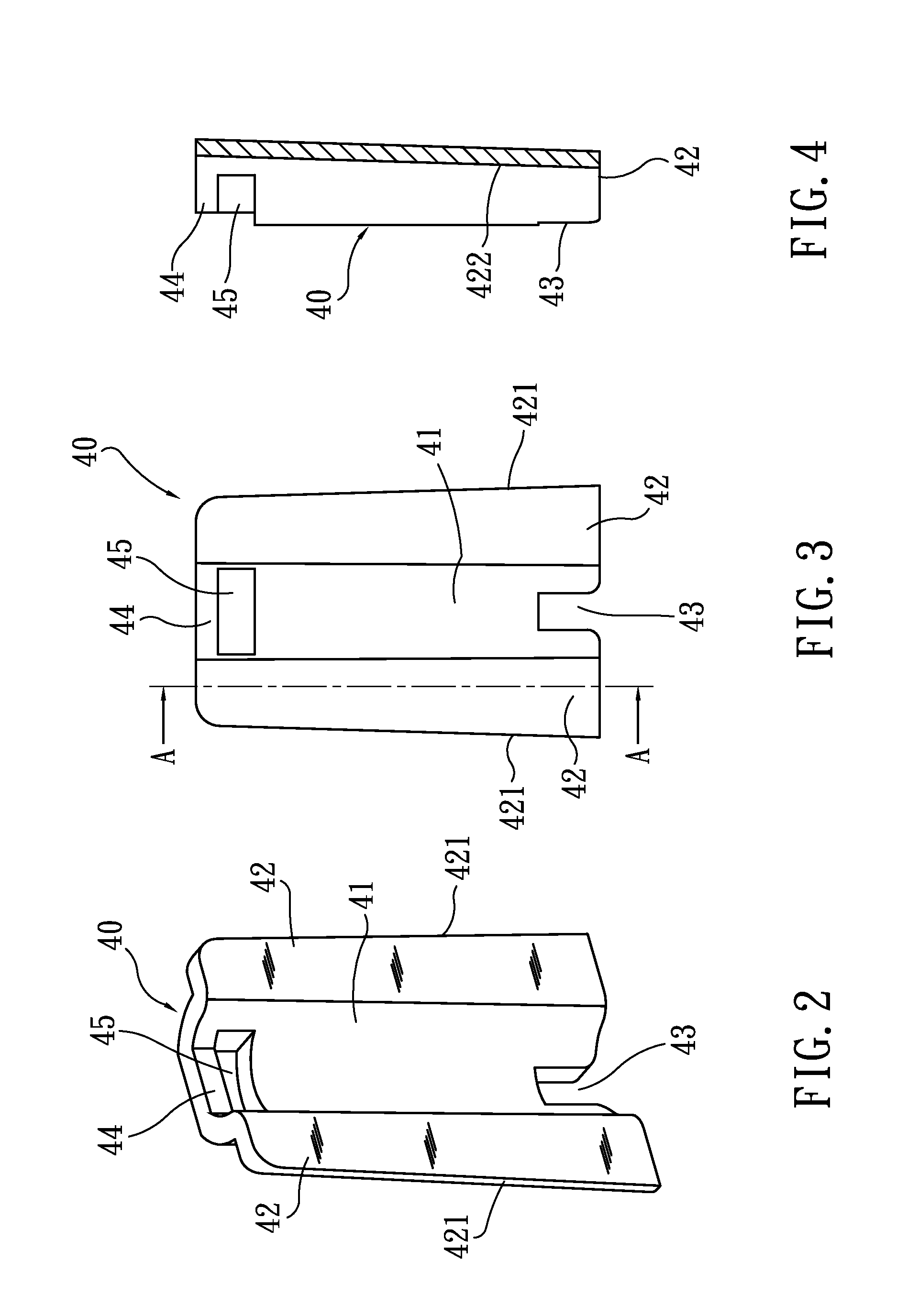
[0009]In the sectional rack of the present invention, each of the wing portions has a width that is increased from an upper end to a lower end of the wing portion, such that a laterally outer end surface of the wing portion is a gradually downward outward inclined surface; and the wing portion has an outside surface that is also a gradually downward outward inclined surface. Each of the C-shaped clamping members includes a pair of hooking portions facing toward each other to define an opening therebetween. Two opposite inner end surfaces of an inner space enclosed in the C-shaped clamping member are downward outward inclined surfaces, so that a width of the inner space of the C-shaped clamping member measured between the two opposite inner end surfaces gradually increases from top to bottom; and an inside surface of each of the two hooking portions facing toward the inner space of the C-shaped clamping member is a downward and outward inclined surface. With the inclined surfaces on the C-shaped clamping member correspondingly and fitly bearing on the inclined surfaces on the wing portions of the clamping member, the C-shaped clamping member is able to produce a tightening effect on the two wing portions and pushes them toward each other, so that the clamping member can more tightly clamp the post in the receiving recess.
[0010]In the sectional rack of the present invention, each of the clamping members is provided on a wall of the receiving recess near an upper end thereof with an inward protrusion extended into the receiving recess, and each of the posts of the vertical supports to be clamped in the receiving recesses is correspondingly provided with a recess for engaging with the protrusion. Through engagement of the protrusion on the clamping member with the recess on the post, the clamping member is held in place on the post without the risk of moving upward, downward, leftward or rightward relative to the post.

Problems solved by technology

The above-structured sectional rack has relatively low structural strength and tends to wobble sidewardly.
Since the crossed tension braces are not suitable for mounting to between the front twin-post supports of the two side support frames, the sectional rack could not have balanced front and rear structural strength.
Thus, the whole sectional rack still has poor structural strength and tends to wobble sidewardly when an external force is applied thereto.

Method used


Image

  • Sectional rack
  • Sectional rack
  • Sectional rack

Examples


Embodiment Construction

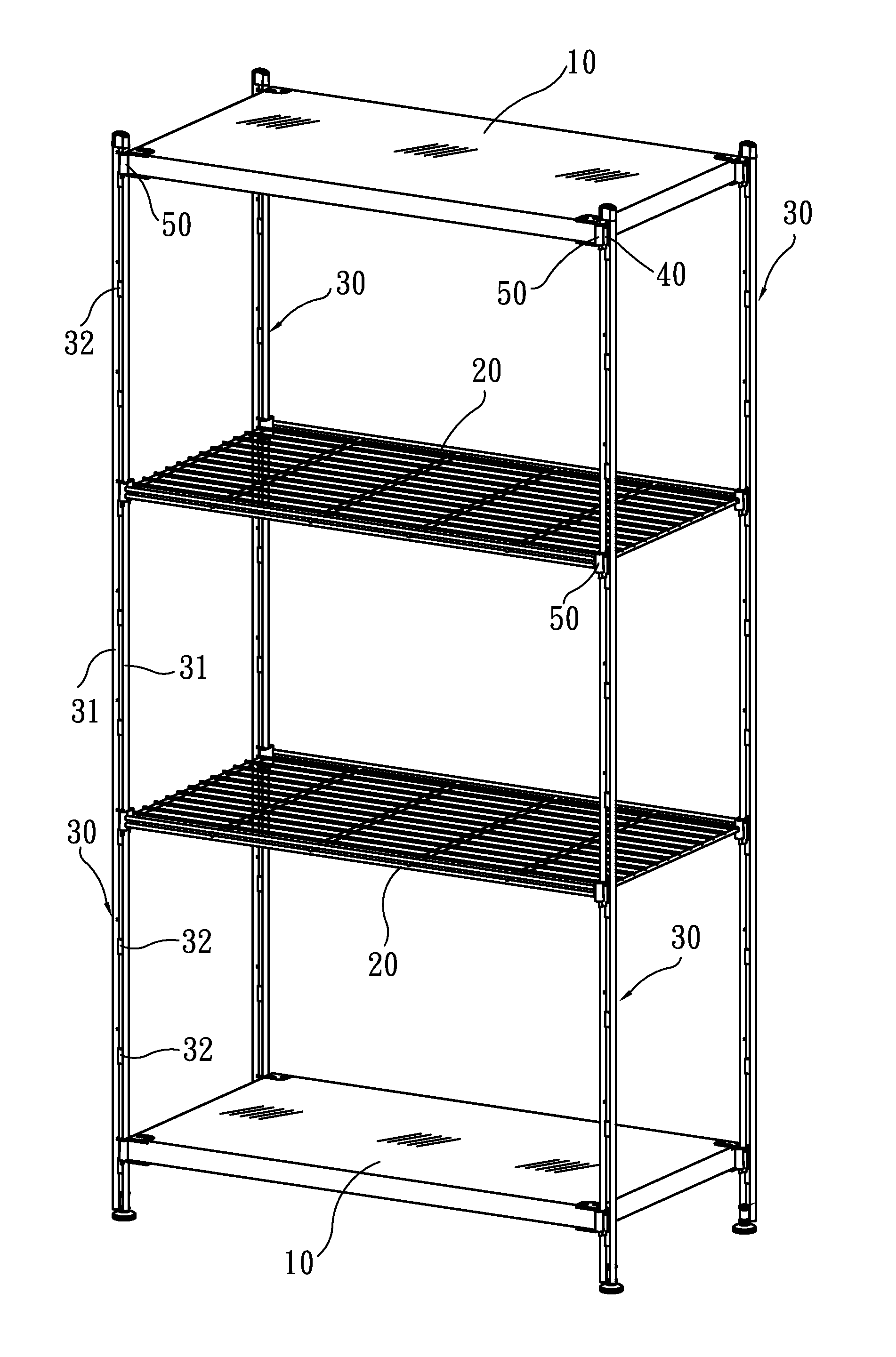
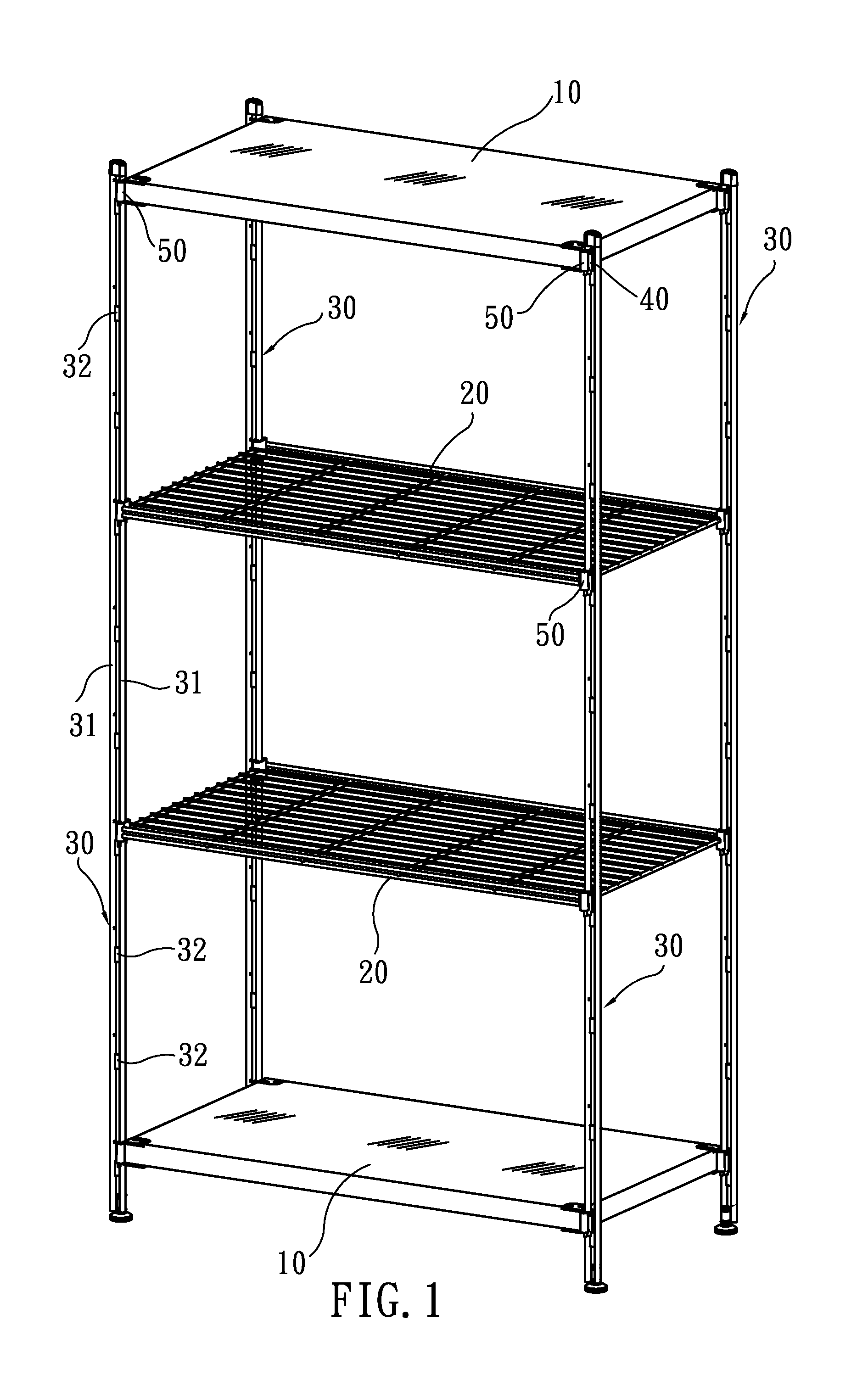
[0028]Please refer to FIG. 1 that is an assembled perspective view of a sectional rack according to an embodiment of the present invention. The sectional rack of the present invention includes at least four vertical supports 30, at least two shelves 10, 20, and a plurality of clamping members 40. In the illustrated embodiment, there are included four vertical supports 30, two shelves 10 that are respectively in the form of a plate, and two shelves 20 that are wire shelves. As shown in FIG. 1, the shelves 10, 20 are respectively connected at four corners to the four vertical supports 30 to provide an assembled sectional rack of the present invention.

[0029]The vertical supports 30 respectively include two laterally juxtaposed posts 31, and a plurality of vertically equally spaced connecting members 32. The connecting members 32 are provided between the two laterally juxtaposed posts 31 of each of the vertical supports 30 to connect the two posts 31 into an integral unit.

[0030]Please r...


PUM

PropertyMeasurementUnit
widthaaaaaaaaaa
sizeaaaaaaaaaa
outer diameteraaaaaaaaaa

Abstract

A sectional rack includes at least four vertical supports, at least two shelves, and a plurality of clamping members. Each of the vertical supports includes two laterally juxtaposed posts. Each of the clamping members defines a vertically extended receiving recess and has two wing portions laterally extended from two opposite lateral edges of an open side of the receiving recess. The receiving recess is sized for one post of the vertical support to partially set therein, allowing the clamping member to assemble to the vertical support. Each of the shelves is provided at each of four corners with an outward-opened C-shaped clamping member for tightly fitting around and thereby pushing the two wing portions of the clamping member toward each other for firmly clamping the post in the receiving recess, so that the four corners of the shelf are firmly connected to the posts of the four vertical supports.

Description

FIELD OF THE INVENTION[0001]The present invention relates to a sectional rack, and more particularly to a sectional rack, of which shelves are tightly connected to four vertical supports through tight fitting of C-shaped clamping members provided at four corners of the shelves around clamping members assembled to the vertical supports, giving the sectional rack an increased structural strength.BACKGROUND OF THE INVENTION[0002]Various types of organizers are provided in homes, offices or other working places for holding or positioning different articles and items. Such organizers can be generally divided into a fixed type that could not be easily disassembled and a sectional type that can be easily disassembled and assembled again. The sectional organizers have the advantages of easy to store and transport to thereby enable reduced storing and transporting costs and accordingly upgraded market competing ability.[0003]The sectional organizers can be further divided into two types, one...

Claims


Application Information

Patent Timeline
Patent Type & Authority Applications(United States)
IPC IPC(8): A47B47/00
CPCA47B47/0083A47B57/265
Inventor CHEN, HENRY
Owner PROTREND ENTERPRISE CO LTD
Learn More