Ribbon microphone with USB output

a microphone and ribbon technology, applied in the direction of transducer details, electrical transducers, electrical equipment, etc., can solve the problems of ribbon microphones, microphones with ribbons, and not adapted for usb inputs commonly employed in electronic equipment, so as to reduce noise and increase signal level

Inactive Publication Date: 2012-11-29
MARSHALL LEONARD +2
View PDF12 Cites 11 Cited by
  • Summary
  • Abstract
  • Description
  • Claims
  • Application Information

AI Technical Summary

Benefits of technology

[0009]It is a further object of the present invention to provide a USB ribbon microphone including a transformer be

Problems solved by technology

However, currently available ribbon diaphragm microphones, or ribbon microphones,

Method used


Image

  • Ribbon microphone with USB output
  • Ribbon microphone with USB output
  • Ribbon microphone with USB output

Examples


Embodiment Construction

[0020]The detailed embodiment of the present invention is disclosed herein. It should be understood, however, that the disclosed embodiment is merely exemplary of the invention, which may be embodied in various forms. Therefore, the details disclosed herein are not to be interpreted as limiting, but merely as a basis for teaching one skilled in the art how to make and / or use the invention.

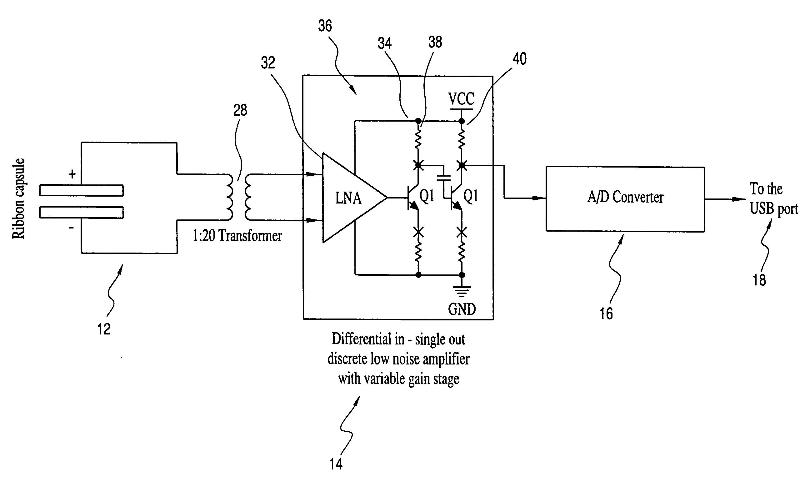
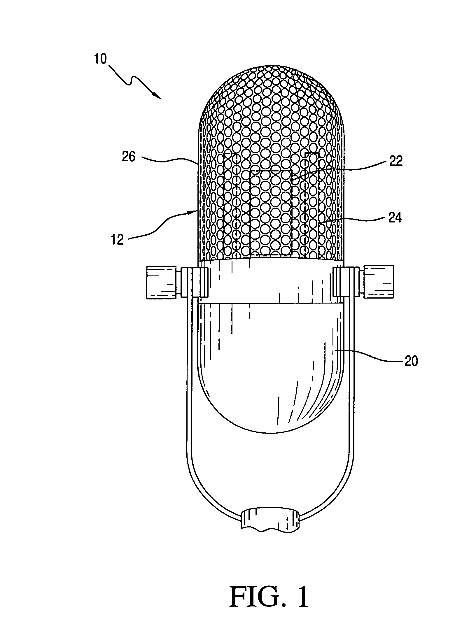
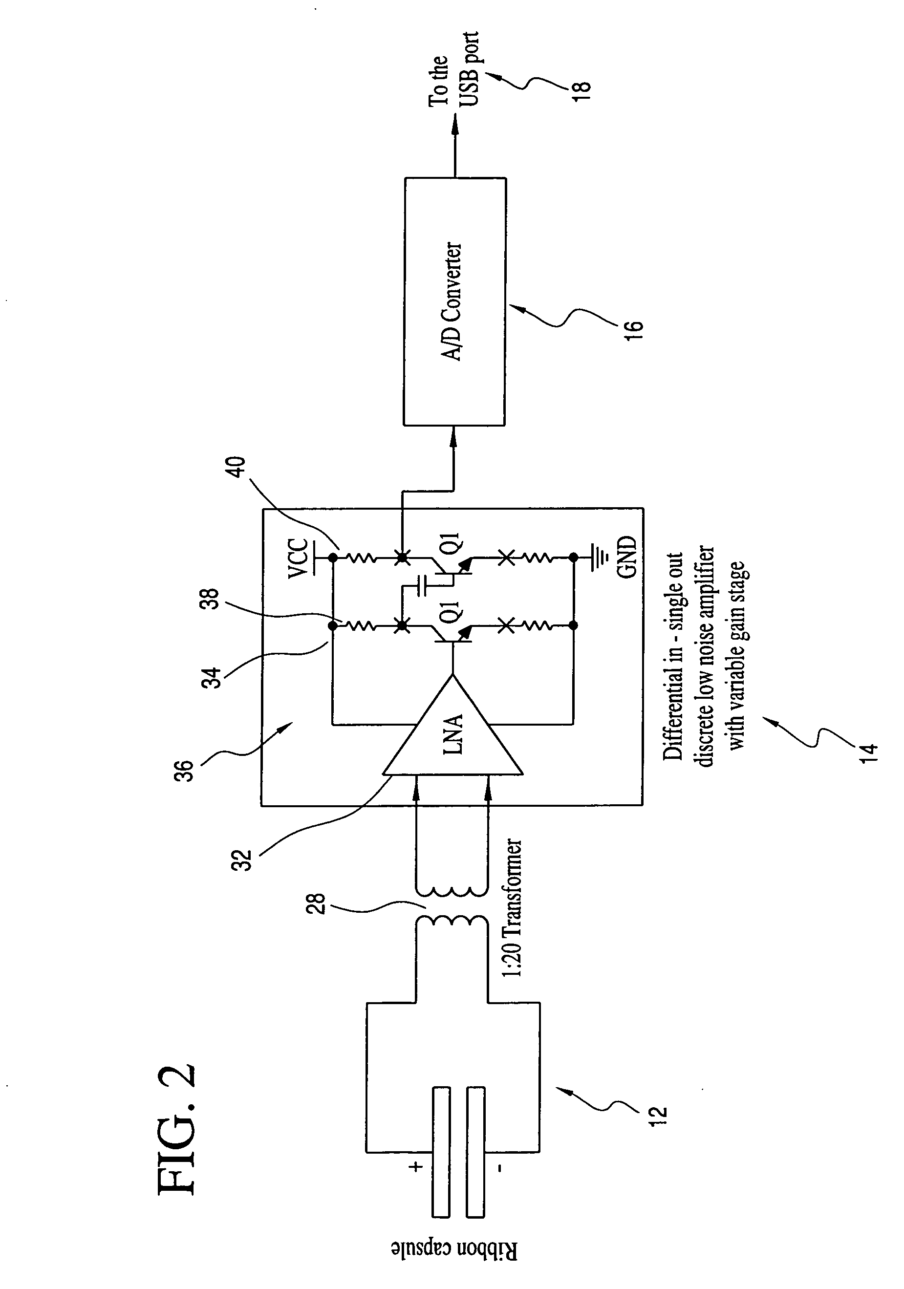
[0021]Referring to FIGS. 1 and 2, a USB ribbon microphone 10 is disclosed. The USB ribbon microphone 10 achieves classic ribbon sound utilizing USB technology and thereby allowing connection of the microphone 10 to audio equipment employing USB inputs, for example, various computers. The USB ribbon microphone 10 generally includes a ribbon diaphragm assembly 12, amplification circuitry 14, A / D converter16 and a USB output port 18. All of the components are maintained within a housing member 20.

[0022]The ribbon diaphragm assembly 12 is electrical connected to the amplification circuitry 14 allowing ...


PUM


Abstract

A USB ribbon microphone includes a ribbon diaphragm assembly, an amplification circuitry connected to the ribbon diaphragm assembly, an A/D converter connected to the amplification circuitry, and a USB output port connected to the A/D converter for selective connection with a USB input.

Description

CROSS REFERENCE TO RELATED APPLICATION[0001]This application claims the benefit of U.S. Application Ser. No. 61 / 490,407, entitled “RIBBON MICROPHONE WITH USB OUTPUT,” filed May 26, 2011BACKGROUND OF THE INVENTION[0002]1. Field of the Invention[0003]The invention relates to ribbon microphones employing a USB output.[0004]2. Description of the Related Art[0005]Microphones with ribbon diaphragms are commonly desired for use by musicians and recording engineers because of their ability to capture high-frequency detail. However, currently available ribbon diaphragm microphones, or ribbon microphones, are not adapted for use with USB inputs commonly employed in electronic equipment.SUMMARY OF THE INVENTION[0006]It is, therefore, an object of the present invention to provide a USB ribbon microphone including a ribbon diaphragm assembly, an amplification circuitry connected to the ribbon diaphragm assembly, an A / D converter connected to the amplification circuitry, and a USB output port con...

Claims


Application Information

Patent Timeline
IPC IPC(8): H04R3/00
CPCH04R3/00H04R2420/09H04R9/08H04R9/048
Inventor MARSHALL, LEONARDMOHANKUMAR, NAHUSHA BHADRAVATISILVA, STEVEN
Owner MARSHALL LEONARD
Why Eureka
Try Eureka