Device for electric power supply of a portable lamp

a portable lamp and electric power supply technology, applied in the direction of electrochemical generators, cell components, lighting and heating apparatuses, etc., can solve the problem of not having the same primary cell, and achieve the effect of costing the devi

Inactive Publication Date: 2012-11-29
ZEDEL CORP
View PDF3 Cites 1 Cited by
  • Summary
  • Abstract
  • Description
  • Claims
  • Application Information

AI Technical Summary

Benefits of technology

[0011]At least one object of the invention is to enable the cost of a device designed to supply electric power to a portable lamp while giving a choice as to the type of power supply, chosen from power supply by primary cell or cells and power supply by storage battery or batteries, to be reduced.
[0013]In addition to achieving the above-mentioned object, the invention can enable one or more additional advantages to be obtained, including smaller space occupation, simplification, easier use, enhanced strength and greater dependability of use.
[0024]Each branch advantageously comprises a wing for securing to a bottom of the housing and for guiding this branch in to-and-fro movement relative to the other branch. This securing and guiding wing is engaged behind a portion of the bottom so as to be secured in the opposite direction to this bottom and to be able to slide in parallel manner to a relative movement of the two branches towards or away from one another. The securing and guiding wings preferably further form arresting stops to stop movement of the two branches towards one another at a minimum clearance value. This minimum value is advantageously chosen such that engagement of the storage battery between the two branches remains an operation that is easy to perform.

Problems solved by technology

However, one difficulty to be overcome is that the primary cell does not have the same format as the storage battery, nor is it connected in the same way in the lamp.

Method used


Image

  • Device for electric power supply of a portable lamp
  • Device for electric power supply of a portable lamp
  • Device for electric power supply of a portable lamp

Examples


case 1

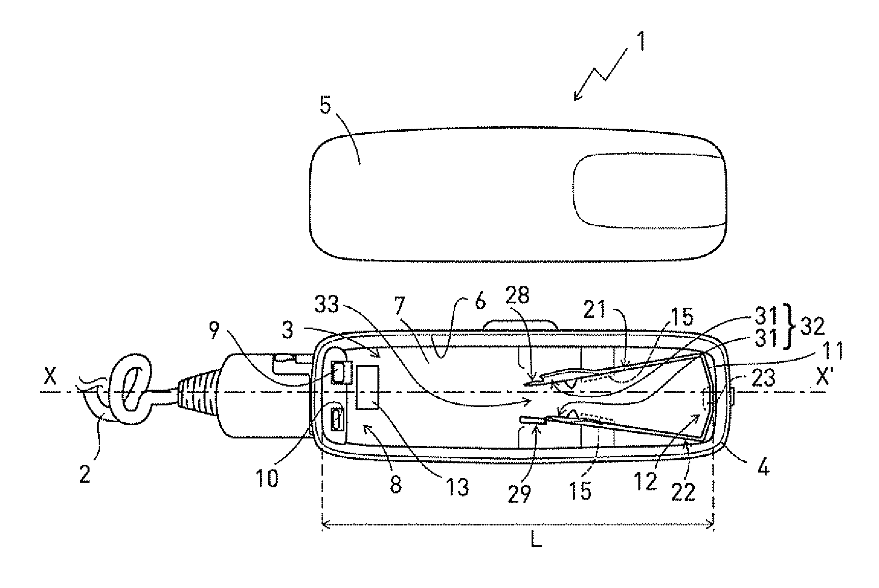
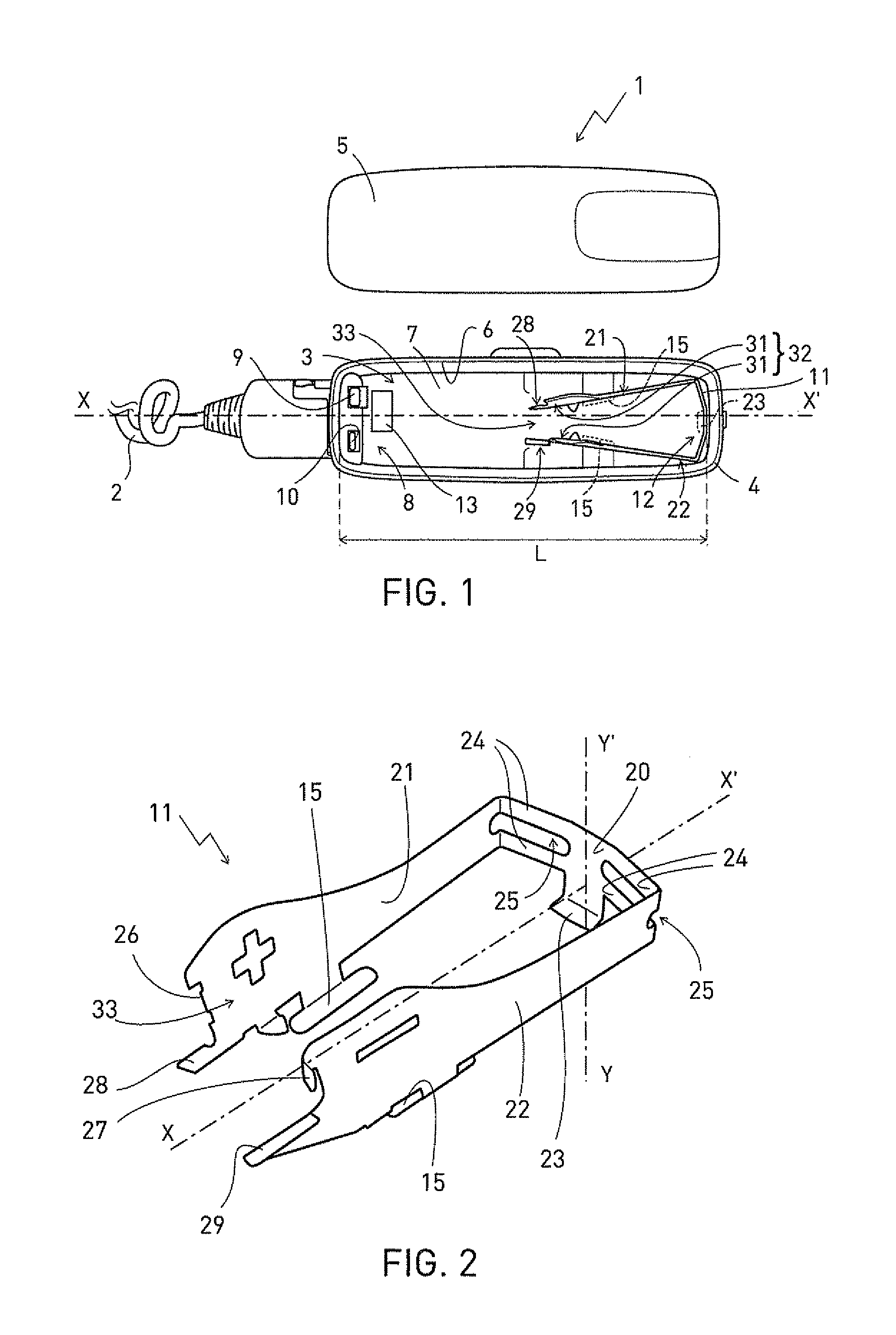
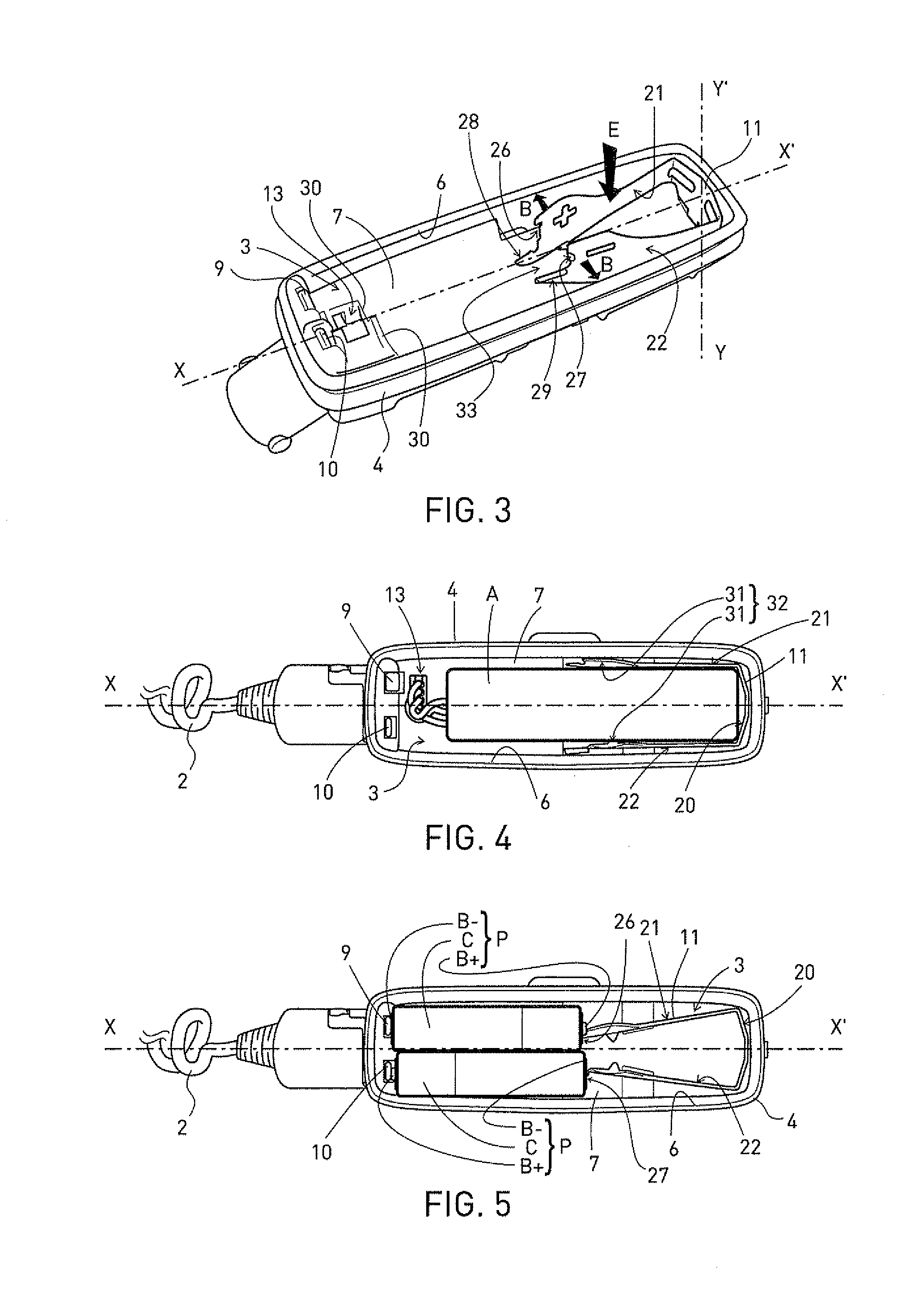
[0036]Case 1 comprises an enclosure in two parts that are dissociable from one another and complementary to one another, each of which partially delineates an internal housing 3. These two parts are a body 4 and a cover 5 for closing an opening 6 providing lateral access to this housing 3. An add-on base 7 forming part of case 1 is fitted in body 4, on the opposite side from opening 6.

[0037]Case 1 and housing 3 are elongate along one and the same longitudinal axis X-X′. Opening 6 extends substantially over the whole length L of housing 3.

[0038]At one end 8 of housing 3, body 4 has two contacts or poles 9 and 10 of opposite polarities, which are transversely offset from one another and are arranged on each side of longitudinal axis X-X′. Each pole 9 or 10 is designed for connection of a terminal of a standard primary cell and forms part of electric connections for connecting either one, as required, of two interchangeable electric power sources, in a circuit for power supply of the p...


PUM

PropertyMeasurementUnit
volumeaaaaaaaaaa
lengthaaaaaaaaaa
electric poweraaaaaaaaaa

Abstract

This device comprises an enclosure and electric connections for connection, in a power supply circuit, with either one of two interchangeable electric power sources, as required. The enclosure delineates a housing accommodating either two primary cells together or a storage battery. A contact for connecting a terminal of one of the primary cells to a terminal of the other primary cell comprises a clamp that is deformable between a first configuration in which each one of two facing branches of the contact is positioned to connect one of said terminals by penetrating into an accommodating volume for accommodating the storage battery, and a second configuration in which the two branches are placed outside said accommodating volume which is left free.

Description

BACKGROUND OF THE INVENTION[0001]The invention relates to the field of portable electric lamps, including lamps called “headlamps” which are worn on the forehead so as to perform lighting in the forward direction, being for example able to be fitted on a helmet. More precisely, the invention relates to an electric power supply device for supplying electric power to a portable lamp, of the kind comprising an enclosure and electric connections for connection, in a power supply circuit, with either one of two interchangeable electric power sources, as required, that are a rechargeable storage battery and a set of at least two primary cells. In the electric power supply device of the kind considered here, the electric connections comprise a contact for connecting a terminal of one of the primary cells to a terminal of the other primary cell, whereas the enclosure delineates a housing for accommodating either the primary cells together or the rechargeable storage battery.STATE OF THE ART...

Claims


Application Information

Patent Timeline
Patent Type & Authority Applications(United States)
IPC IPC(8): H01M16/00H01M50/209
CPCF21L4/00H01M2/1066H01M2/1055Y02E60/10H01M50/209H01M50/213
Inventor BOUFFAY, BORISBERREL, PHILIPPE
Owner ZEDEL CORP
Why Eureka
Try Eureka