Antenna mounting structure of electronic device
- Summary
- Abstract
- Description
- Claims
- Application Information
AI Technical Summary
Problems solved by technology
Method used
Image


Examples
Embodiment Construction
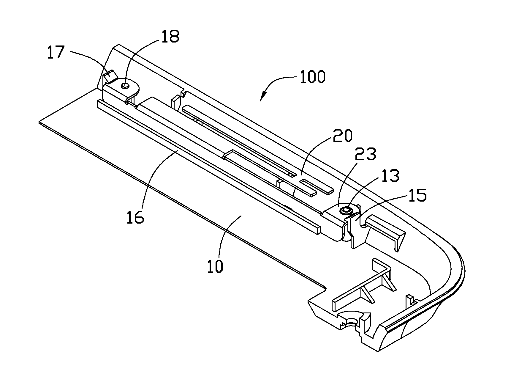
[0010]Referring to FIG. 1, an antenna mounting structure 100 of an electronic device according to a first embodiment of the present disclosure is shown. The electronic device can be, for example, a portable DVD player, a notebook computer or a projector. The antenna mounting structure 100 includes a casing 10 and an antenna 20.
[0011]Referring also to FIG. 2, the casing 10 includes a bottom wall 11 and a sidewall 12 extending from the bottom wall 11. The bottom wall 11 forms a first pin 13 and a second pin 18 near the sidewall 12. Spaced from the sidewall 12 the first pin 13 and the second pin 18 extend perpendicularly from the bottom wall 11. A first rib 14 connects the first fin 13 with the sidewall 12. A height of the first rib 14 is slightly less than that of the first pin 13. A plurality of second ribs 19 radially extends from the second pin 18. One of the second ribs 19 connects the second pin 18 with the sidewall 12. A height of each second rib 19 is slightly less than that of...
PUM
 Abstract
Description
Claims
Application Information